Preliminary Information
MT9076
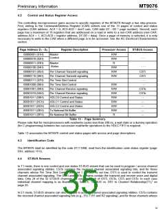
7.2.1
External Data Link
In T1 mode, MT9076 has two pairs of pins (TxDL and TxDLCLK, RxDL and RxDLCLK) dedicated to
transmitting and receiving bits in the selected overhead bit positions. Pins TxDLCLK and RxDLCLK are clock
outputs available for clocking data into the MT9076 (for transmit) or external device (for receive information).
Each clock operates at 4 Khz. In the SLC-96 mode the optional serial data link is multiplexed into the Fs bit
position. In the ESF mode, the serial data link is multiplexed into odd frames, i.e. the FDL bit positions.
7.2.2
Bit - Oriented Messaging
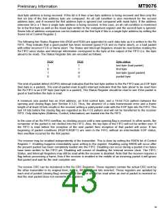
In T1 mode, MT9076 Bit oriented messaging may be selected by setting bit 6 (BIOMEn) in the Data Link
Control Word (page 1H, address 12H). The transmit data link will contain the repeating serial data stream
111111110xxxxxx0 where the byte 0xxxxxx0 originates from the user programmed register "Transmit Bit
Oriented Message" - page 1H address 13H. The receive BIOM register "Receive Bit Oriented Message" - page
3H, address 15H, will contain the last received valid message (the 0xxxxxx0 portion of the incoming serial bit
stream). To prevent spurious inputs from creating false messages, a new message must be present in 7 of the
last 10 appropriate byte positions before being loaded into the receive BIOM register. When a new message
has been received, a maskable interrupt (maskable by setting bit 1 low in Interrupt Mask Word Three - page
1H, address 1EH) may occur.
8.0 Floating HDLC Channels
MT9076 has three embedded HDLC controllers (HDLC0, HDLC1, HDLC2) each of which includes the following
features:
•
•
Independent transmit and receive FIFO's;
Receive FIFO maskable interrupts for nearly full (programmable interrupt levels) and overflow
conditions;
•
Transmit FIFO maskable interrupts for nearly empty (programmable interrupt levels) and underflow
conditions;
•
•
•
Maskable interrupts for transmit end-of-packet and receive end-of-packet;
Maskable interrupts for receive bad-frame (includes frame abort);
Transmit end-of-packet and frame-abort functions.
Each controller may be attached to any of the active 64 Kkb/s channels (24 in the case of T1, 31 in the case of
E1). HDLC0 may also be attached to the FDL in a T1 ESF link by connecting it to phantom channel 31 when
programming the HDLC Select Word. If HDLC0 is attached to channel 0 in E1 mode, only the activated Sa bits
(as per the Multiframe and Data Selection Word) will be transmit and received by the controller.
8.1
Channel Assignment
In T1 mode, any DS1 channel can be connected to either of HDLC0,1 or 2, operating at 56 or 64 Kb/s. Setting
control bit H1R64 (address 12 H on page 01H) high selects 64 Kb/s operation for all HDLCs. Setting this bit low
selects 56 Kb/s for all HDLC. Interrupts from any of the HDLCs are masked when they are disconnected.
In E1 mode, all PCM-30 channels except channel 0 can be connected to either of HDLC0,1 or 2. HDLC1 and
HDLC2 operate at 64 Kb/s. HDLC0 operates at 64 kb/s when connected to any of channels 1 to 31. When
connected to channel 0 HDLC0 operates at 4, 8, 12, 16 or 20 Kb/s depending on the number of activated Sa
bits.
HDLCs can be activated by programming the HDLC Select Words (page 02H, addresses 19H, 1AH and 1BH
for HDLC0, HDLC1 and HDLC2 respectively).
35

 MITEL [ MITEL NETWORKS CORPORATION ]