VDP 313xY
ADVANCE INFORMATION
2.10.7.Chrominance Transient Improvement
2.10.8.Inverse Matrix
The intention of this block is to enhance the chromi-
nance resolution. A correction signal is calculated by
differentiation of the color difference signals. The differ-
entiation can be selected according to the signal band-
width, e.g. for PAL/NTSC/SECAM or digital component
signals, respectively. The amplitude of the correction
signal is adjustable. Small noise amplitudes in the cor-
rection signal are suppressed by an adjustable coring
circuit. To eliminate ‘wrong colors’, which are caused
by over and undershoots at the chrominance transi-
tion, the sharpened chrominance signals are limited to
a proper value automatically.
A 6-multiplier matrix transcodes the CR and CB signals
to R-Y, B-Y, and G-Y. The multipliers are also used to
adjust color saturation in the range of 0 to 2. The coef-
ficients are signed and have a resolution of 9 bits. The
matrix computes:
R−Y = MR1×CB+MR2×CR
G−Y = MG1×CB+MG2×CR
B−Y = MB1×CB+MB2×CR
The initialization values for the matrix are computed
from the standard ITUR (CCIR) matrix:
R
G
B
1
1
1
0
1.402
−0.713
0
Y
CB
CR
−0.345
1.773
=
L
a)
For a contrast setting of CTM+32, the matrix values
are scaled by a factor of 64 (see Table 2–5 on
page 32).
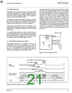
CR in
CB in
2.10.9.RGB Processing
t
After adding the post-processed luminance, the digital
RGB signals are limited to 10 bits. Three multipliers
are used to digitally adjust the whitedrive. An average
beam current limiter using the same multipliers is
implemented (see Section 2.11.1. on page 21).
b)
Ampl.
2.10.10.Picture Frame Generator
t
When the picture does not fill the total screen (height
or width too small) it is surrounded with black areas.
These areas (and more) can be colored with the pic-
ture frame generator. This is done by switching over
the RGB signal from the matrix to the signal from the
internal picture frame generator.
c)
CR out
CB out
t
The width of each area (left, right, upper, lower) can be
adjusted separately. The generator starts on the right,
respectively lower side of the screen and stops on the
left, respectively upper side of the screen. This means,
it runs during horizontal, respectively vertical flyback.
The color of the complete border can be programmed
in the format 3 × 4 bit RGB. The contrast can be
adjusted separately.
a) CRCB input of DTI
b) CRCB input + Correction signal
c) sharpened and limited CRCB
Fig. 2–15: Digital Color Transient Improvement
18
Micronas

 MICRONAS [ MICRONAS ]