ADVANCE INFORMATION
VDP 313xY
2.10.4.Digital Brightness Adjustment
2.10.6.Chrominance Interpolation
The DC-level of the luminance signal can be adjusted
by adding/subtracting an 8-bit number in the lumi-
nance signal path in front of the softlimiter.
A linear phase interpolator is used to convert the
chrominance sampling rate from 10.125 MHz (4:2:2) to
20.25 MHz (4:4:4). All further processing is carried out
at the full sampling rate.
After the brightness addition, the negative going sig-
nals are limited to zero. It is desirable to keep a small
positive offset with the signal to prevent undershoots
produced by the peaking from being cut.
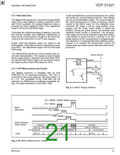
2.10.5.Soft Limiter
The dynamic range of the processed luminance signal
must be limited to prevent the CRT from overload. An
appropriate headroom for contrast, peaking and bright-
ness can be adjusted by the TV manufacturer accord-
ing to the CRT characteristics. All signals above this
limit will be soft-clipped. A characteristic diagram of the
soft limiter is shown in Fig. 2–14. The total limiter con-
sists of three parts:
1. Part 1 includes adjustable tilt point and gain. The
gain before the tilt value is 1. Above the tilt value, a
part (0...15/16) of the input signal is subtracted from
the input signal itself. Therefore the gain is adjust-
able from 16/16 to 1/16, when the slope value varies
from 0 to 15. The tilt value can be adjusted from 0 to
511.
2. Part 2 has the same characteristics as part 1. The
subtracting part is also relative to the input signal,
so the total differential gain will become negative if
the sum of slope 1 and slope 2 is greater than 16
and the input signal is above the both tilt values (see
characteristics).
3. Finally, the output signal of the soft limiter will be
clipped by a hard limiter adjustable from 256 to 511.
Output
Part 1
Part 2
Hard limiter
Calculation Example for the
511
0
Softlimiter Input Amplitude.
(The real signal processing in
the limiter is 2 bit more than
described here)
slope 1
[0..15]
2
4
6
0
2
4
400
300
200
100
0
8
10
12
Y Input
16..235 (ITUR)
range=
256..511
Black Level
Contrast
Dig. Brightness
BLE
16 (constant)
6
8
10
63
20
off
off
14
slope 2
[0..15]
12
14
Peaking
Limiter input signal:
(Yin-Black Level) Contr./32 + Brightn.
(235-16) 63/32 + 20 = 451
tilt 1 [ 0..511]
tilt 2 [ 0..511]
Limiter Input
0
100
200
300
400
500
600
700
800
900
1023
Fig. 2–14: Characteristic of soft limiter a and b and hard limiter
Micronas
17

 MICRONAS [ MICRONAS ]