PIC24FJ64GA104 FAMILY
10.4.1
AVAILABLE PINS
10.3 Input Change Notification
The Peripheral Pin Select feature is used with a range
of up to 25 pins, depending on the particular device and
its pin count. Pins that support the Peripheral Pin
Select feature include the designation “RPn” in their full
pin designation, where “n” is the remappable pin
number.
The input change notification function of the I/O ports
allows the PIC24FJ64GA104 family of devices to gen-
erate interrupt requests to the processor in response to
a Change-of-State (COS) on selected input pins. This
feature is capable of detecting input Change-of-States
even in Sleep mode, when the clocks are disabled.
Depending on the device pin count, there are up to
31 external inputs that may be selected (enabled) for
generating an interrupt request on a Change-of-State.
See Table 1-2 for a summary of pinout options in each
package offering.
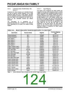
10.4.2
AVAILABLE PERIPHERALS
Registers, CNEN1 and CNEN2, contain the interrupt
enable control bits for each of the CN input pins. Setting
any of these bits enables a CN interrupt for the
corresponding pins.
The peripherals managed by the Peripheral Pin Select
are all digital only peripherals. These include general
serial communications (UART and SPI), general
purpose timer clock inputs, timer related peripherals
(input capture and output compare) and external
interrupt inputs. Also included are the outputs of the
comparator module, since these are discrete digital
signals.
Peripheral Pin Select is not available for I2C™ change
notification inputs, RTCC alarm outputs or peripherals
with analog inputs.
Each CN pin has a weak pull-up connected to it. The
pull-up acts as a current source that is connected to the
pin. This eliminates the need for external resistors
when push button or keypad devices are connected.
The pull-ups are separately enabled using the CNPU1
and CNPU2 registers (for pull-ups). Each CN pin has
individual control bits for its pull-up. Setting a control bit
enables the weak pull-up for the corresponding pin.
When the internal pull-up is selected, the pin pulls up to
VDD – 0.7V (typical). Make sure that there is no external
pull-up source when the internal pull-ups are enabled,
as the voltage difference can cause a current path.
A key difference between pin select and non pin select
peripherals is that pin select peripherals are not asso-
ciated with a default I/O pin. The peripheral must
always be assigned to a specific I/O pin before it can be
used. In contrast, non pin select peripherals are always
available on a default pin, assuming that the peripheral
is active and not conflicting with another peripheral.
Note:
Pull-ups on change notification pins
should always be disabled whenever the
port pin is configured as a digital output.
10.4.2.1
Peripheral Pin Select Function
Priority
10.4 Peripheral Pin Select (PPS)
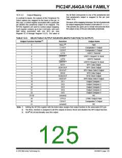
Pin-selectable peripheral outputs (for example, OC and
UART transmit) take priority over any general purpose
digital functions permanently tied to that pin, such as
PMP and port I/O. Specialized digital outputs, such as
USB functionality, take priority over PPS outputs on the
same pin. The pin diagrams at the beginning of this
data sheet list peripheral outputs in order of priority.
Refer to them for priority concerns on a particular pin.
A major challenge in general purpose devices is provid-
ing the largest possible set of peripheral features while
minimizing the conflict of features on I/O pins. In an
application that needs to use more than one peripheral
multiplexed on a single pin, inconvenient work arounds
in application code or a complete redesign may be the
only option.
The Peripheral Pin Select feature provides an alternative
to these choices by enabling the user’s peripheral set
selection and their placement on a wide range of I/O
pins. By increasing the pinout options available on a par-
ticular device, users can better tailor the microcontroller
to their entire application, rather than trimming the
application to fit the device.
Unlike devices with fixed peripherals, pin-selectable
peripheral inputs never take ownership of a pin. The
pin’s output buffer is controlled by the pin’s TRIS bit
setting, or by a fixed peripheral on the pin. If the pin is
configured in Digital mode, then the PPS input will
operate correctly, reading the input. If an analog func-
tion is enabled on the same pin, the pin-selectable
input will be disabled.
The Peripheral Pin Select feature operates over a fixed
subset of digital I/O pins. Users may independently
map the input and/or output of any one of many digital
peripherals to any one of these I/O pins. Peripheral Pin
Select is performed in software and generally does not
require the device to be reprogrammed. Hardware
safeguards are included that prevent accidental or
spurious changes to the peripheral mapping once it has
been established.
2010 Microchip Technology Inc.
DS39951C-page 123

 MICROCHIP [ MICROCHIP ]