PIC18F2480/2580/4480/4580
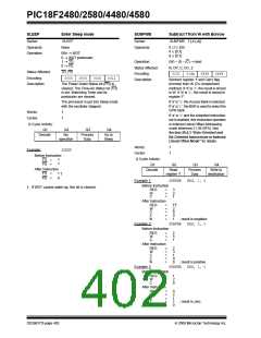
SUBLW
Subtract W from Literal
SUBWF
Subtract W from f
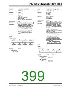
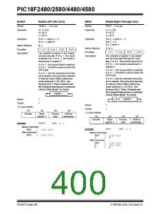
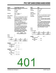
Syntax:
SUBLW
k
Syntax:
SUBWF f {,d {,a}}
Operands:
Operation:
Status Affected:
Encoding:
Description:
0 ≤ k ≤ 255
Operands:
0 ≤ f ≤ 255
d ∈ [0,1]
a ∈ [0,1]
k – (W) → W
N, OV, C, DC, Z
Operation:
(f) – (W) → dest
0000
1000
kkkk
kkkk
Status Affected:
Encoding:
N, OV, C, DC, Z
W is subtracted from the eight-bit
literal ‘k’. The result is placed in W.
0101
11da
ffff
ffff
Description:
Subtract W from register ‘f’ (2’s
complement method). If ‘d’ is ‘0’, the
result is stored in W. If ‘d’ is ‘1’, the
result is stored back in register ‘f’.
Words:
Cycles:
1
1
Q Cycle Activity:
Q1
If ‘a’ is ‘0’, the Access Bank is selected.
If ‘a’ is ‘1’, the BSR is used to select the
GPR bank.
Q2
Q3
Q4
Decode
Read
literal ‘k’
Process
Data
Write to W
If ‘a’ is ‘0’ and the extended instruction
set is enabled, this instruction operates
in Indexed Literal Offset Addressing
mode whenever f ≤ 95 (5Fh). See
Section 26.2.3 “Byte-Oriented and
Bit-Oriented Instructions in Indexed
Literal Offset Mode” for details.
Example 1:
SUBLW 02h
Before Instruction
W
C
=
=
01h
?
After Instruction
W
C
Z
=
01h
=
=
=
1
0
0
; result is positive
Words:
Cycles:
1
1
N
Example 2:
Before Instruction
SUBLW 02h
Q Cycle Activity:
Q1
Q2
Q3
Q4
W
C
=
=
02h
?
Decode
Read
register ‘f’
Process
Data
Write to
destination
After Instruction
W
C
Z
=
00h
Example 1:
SUBWF
REG, 1, 0
=
=
=
1
1
0
; result is zero
Before Instruction
REG
W
C
=
=
=
3
2
?
N
Example 3:
Before Instruction
SUBLW 02h
After Instruction
REG
W
C
Z
N
=
1
2
1
0
0
W
C
=
=
03h
?
=
=
=
=
; result is positive
After Instruction
W
C
Z
=
FFh; (2’s complement)
=
=
=
0
0
1
; result is negative
Example 2:
Before Instruction
SUBWF
REG, 0, 0
N
REG
W
C
=
=
=
2
2
?
After Instruction
REG
W
C
=
2
0
1
1
0
=
=
=
=
; result is zero
Z
N
Example 3:
Before Instruction
SUBWF
REG, 1, 0
REG
W
C
=
=
=
1
2
?
After Instruction
REG
W
C
=
FFh ;(2’s complement)
2
0
0
1
=
=
=
=
; result is negative
Z
N
© 2009 Microchip Technology Inc.
DS39637D-page 403

 MICROCHIP [ MICROCHIP ]