PIC18F2450/4450
11.3.3
TIMER1 OSCILLATOR LAYOUT
CONSIDERATIONS
11.5 Resetting Timer1 Using the CCP
Special Event Trigger
The Timer1 oscillator circuit draws very little power
during operation. Due to the low-power nature of the
oscillator, it may also be sensitive to rapidly changing
signals in close proximity.
If the CCP module is configured in Compare mode
to
generate
a
Special
Event
Trigger
(CCP1M3:CCP1M0 = 1011), this signal will reset
Timer1. The trigger from CCP1 will also start an A/D
conversion if the A/D module is enabled (see
Section 13.3.4 “Special Event Trigger” for more
information).
The oscillator circuit, shown in Figure 11-3, should be
located as close as possible to the microcontroller.
There should be no circuits passing within the oscillator
circuit boundaries other than VSS or VDD.
The module must be configured as either a timer or a
synchronous counter to take advantage of this feature.
When used this way, the CCPRH:CCPRL register pair
effectively becomes a period register for Timer1.
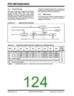
If a high-speed circuit must be located near the oscilla-
tor (such as the CCP1 pin in Output Compare or PWM
mode, or the primary oscillator using the OSC2 pin), a
grounded guard ring around the oscillator circuit, as
shown in Figure 11-4, may be helpful when used on a
single-sided PCB or in addition to a ground plane.
If Timer1 is running in Asynchronous Counter mode,
this Reset operation may not work.
In the event that a write to Timer1 coincides with a
Special Event Trigger, the write operation will take
precedence.
FIGURE 11-4:
OSCILLATOR CIRCUIT
WITH GROUNDED
GUARD RING
Note:
The Special Event Triggers from the
CCP1 module will not set the TMR1IF
interrupt flag bit (PIR1<0>).
VDD
VSS
11.6 Using Timer1 as a Real-Time
Clock
OSC1
OSC2
Adding an external LP oscillator to Timer1 (such as the
one described in Section 11.3 “Timer1 Oscillator”)
gives users the option to include RTC functionality to
their applications. This is accomplished with an
inexpensive watch crystal to provide an accurate time
base and several lines of application code to calculate
the time. When operating in Sleep mode and using a
battery or supercapacitor as a power source, it can
completely eliminate the need for a separate RTC
device and battery backup.
RC0
RC1
RC2
Note: Not drawn to scale.
The application code routine, RTCisr, shown in
Example 11-1, demonstrates a simple method to
increment a counter at one-second intervals using an
Interrupt Service Routine. Incrementing the TMR1
register pair to overflow triggers the interrupt and calls
the routine which increments the seconds counter by
one. Additional counters for minutes and hours are
incremented as the previous counter overflows.
11.4 Timer1 Interrupt
The TMR1 register pair (TMR1H:TMR1L) increments
from 0000h to FFFFh and rolls over to 0000h. The
Timer1 interrupt, if enabled, is generated on overflow
which is latched in interrupt flag bit, TMR1IF
(PIR1<0>). This interrupt can be enabled or disabled
by setting or clearing the Timer1 Interrupt Enable bit,
TMR1IE (PIE1<0>).
Since the register pair is 16 bits wide, counting up to
overflow the register directly from a 32.768 kHz clock
would take 2 seconds. To force the overflow at the
required one-second intervals, it is necessary to
preload it. The simplest method is to set the MSb of
TMR1H with a BSF instruction. Note that the TMR1L
register is never preloaded or altered; doing so may
introduce cumulative error over many cycles.
For this method to be accurate, Timer1 must operate in
Asynchronous mode and the Timer1 overflow interrupt
must be enabled (PIE1<0> = 1) as shown in the
routine, RTCinit. The Timer1 oscillator must also be
enabled and running at all times.
DS39760A-page 118
Advance Information
© 2006 Microchip Technology Inc.

 MICROCHIP [ MICROCHIP ]