PIC18CXX2
7.0.1
INTCON REGISTERS
The INTCON Registers are readable and writable
registers, which contains various enable, priority and
flag bits.
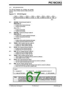
Register 7-1: INTCON Register
R/W-0
R/W-0
R/W-0
R/W-0
R/W-0
RBIE
R/W-0
R/W-0
INT0IF
R/W-x
RBIF
GIE/GIEH
PEIE/GIEL
TMR0IE
INT0IE
TMR0IF
bit 7
bit 0
bit 7
GIE/GIEH: Global Interrupt Enable bit
When IPEN = 0:
1= Enables all un-masked interrupts
0= Disables all interrupts
When IPEN = 1:
1= Enables all interrupts
0= Disables all interrupts
bit 6
PEIE/GEIL: Peripheral Interrupt Enable bit
When IPEN = 0:
1= Enables all un-masked peripheral interrupts
0= Disables all peripheral interrupts
When IPEN = 1:
1= Enables all low priority peripheral interrupts
0= Disables all priority peripheral interrupts
bit 5
bit 4
bit 3
bit 2
bit 1
bit 0
TMR0IE: TMR0 Overflow Interrupt Enable bit
1= Enables the TMR0 overflow interrupt
0= Disables the TMR0 overflow interrupt
INT0IE: INT0 External Interrupt Enable bit
1= Enables the INT0 external interrupt
0= Disables the INT0 external interrupt
RBIE: RB Port Change Interrupt Enable bit
1= Enables the RB port change interrupt
0= Disables the RB port change interrupt
TMR0IF: TMR0 Overflow Interrupt Flag bit
1= TMR0 register has overflowed (must be cleared in software)
0= TMR0 register did not overflow
INT0IF: INT0 External Interrupt Flag bit
1= The INT0 external interrupt occurred (must be cleared in software)
0= The INT0 external interrupt did not occur
RBIF: RB Port Change Interrupt Flag bit
1= At least one of the RB7:RB4 pins changed state (must be cleared in software)
0= None of the RB7:RB4 pins have changed state
Legend:
R = Readable bit
W = Writable bit
U = Unimplemented bit, read as ‘0’
’0’ = Bit is cleared x = Bit is unknown
- n = Value at POR reset
’1’ = Bit is set
Note: Interrupt flag bits get set when an interrupt condition occurs, regardless of the state
of its corresponding enable bit or the global enable bit. User software should ensure
the appropriate interrupt flag bits are clear prior to enabling an interrupt. This feature
allows for software polling.
7/99 Microchip Technology Inc.
Preliminary
DS39026B-page 67

 MICROCHIP [ MICROCHIP ]