PIC18CXX2
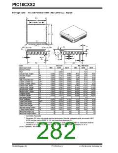
Package Type: 44-Lead Plastic Leaded Chip Carrier (L) – Square
E1
E
# leads = n1
D1
D
n 1 2
α
A3
CH2 x 45°
CH1 x 45°
R1
c
L
A
35°
A1
B1
B
R2
β
A2
p
E2
D2
Units
INCHES*
NOM
44
MILLIMETERS
Dimension Limits
Number of Pins
Pitch
Overall Pack. Height
Shoulder Height
Standoff
MIN
MAX
MIN
NOM
44
MAX
n
p
A
A1
A2
A3
CH1
CH2
E1
D1
E
D
E2
D2
n1
c
B1
B
0.050
0.173
0.103
0.023
0.029
0.045
0.005
0.690
0.690
0.653
0.653
0.620
0.620
11
0.010
0.029
0.018
0.058
0.005
0.025
5
1.27
0.165
0.180
4.19
2.41
0.38
0.61
1.02
0.00
17.40
17.40
16.51
16.51
15.49
15.49
4.38
2.60
0.57
0.74
1.14
0.13
17.53
17.53
16.59
16.59
15.75
15.75
11
4.57
2.79
0.76
0.86
1.27
0.095
0.015
0.024
0.040
0.000
0.685
0.685
0.650
0.650
0.610
0.610
0.110
0.030
0.034
0.050
0.010
0.695
0.695
0.656
0.656
0.630
0.630
Side 1 Chamfer Dim.
Corner Chamfer (1)
Corner Chamfer (other)
Overall Pack. Width
Overall Pack. Length
Molded Pack. Width
Molded Pack. Length
Footprint Width
Footprint Length
Pins along Width
Lead Thickness
Upper Lead Width
Lower Lead Width
Upper Lead Length
Shoulder Inside Radius
J-Bend Inside Radius
Mold Draft Angle Top
Mold Draft Angle Bottom
*
0.25
17.65
17.65
16.66
16.66
16.00
16.00
‡
‡
0.008
0.026
0.015
0.050
0.003
0.015
0
0.012
0.032
0.021
0.065
0.010
0.035
10
0.20
0.66
0.38
1.27
0.08
0.38
0
0.25
0.74
0.46
1.46
0.13
0.64
5
0.30
0.81
0.53
1.65
0.25
0.89
10
†
L
R1
R2
α
β
0
5
10
0
5
10
Controlling Parameter.
†
Dimension “B1” does not include dam-bar protrusions. Dam-bar protrusions shall not exceed 0.003”
(0.076 mm) per side or 0.006” (0.152 mm) more than dimension “B1.”
‡
Dimensions “D” and “E” do not include mold flash or protrusions. Mold flash or protrusions shall not
exceed 0.010" (0.254 mm) per side or 0.020" (0.508 mm) more than dimensions “D” or “E.”
JEDEC equivalent: MO-047 AC
DS39026B-page 282
Preliminary
7/99 Microchip Technology Inc.

 MICROCHIP [ MICROCHIP ]