PIC18F6525/6621/8525/8621
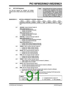
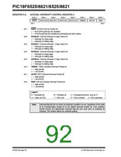
REGISTER 9-2:
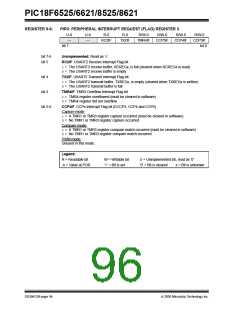
INTCON2: INTERRUPT CONTROL REGISTER 2
R/W-1
RBPU
R/W-1
R/W-1
R/W-1
R/W-1
R/W-1
R/W-1
R/W-1
RBIP
INTEDG0 INTEDG1 INTEDG2 INTEDG3 TMR0IP
INT3IP
bit 7
bit 0
bit 7
bit 6
bit 5
bit 4
bit 3
bit 2
bit 1
bit 0
RBPU: PORTB Pull-up Enable bit
1= All PORTB pull-ups are disabled
0= PORTB pull-ups are enabled by individual port latch values
INTEDG0: External Interrupt 0 Edge Select bit
1= Interrupt on rising edge
0= Interrupt on falling edge
INTEDG1: External Interrupt 1 Edge Select bit
1= Interrupt on rising edge
0= Interrupt on falling edge
INTEDG2: External Interrupt 2 Edge Select bit
1= Interrupt on rising edge
0= Interrupt on falling edge
INTEDG3: External Interrupt 3 Edge Select bit
1= Interrupt on rising edge
0= Interrupt on falling edge
TMR0IP: TMR0 Overflow Interrupt Priority bit
1= High priority
0= Low priority
INT3IP: INT3 External Interrupt Priority bit
1= High priority
0= Low priority
RBIP: RB Port Change Interrupt Priority bit
1= High priority
0= Low priority
Legend:
R = Readable bit
-n = Value at POR
W = Writable bit
‘1’ = Bit is set
U = Unimplemented bit, read as ‘0’
‘0’ = Bit is cleared x = Bit is unknown
Note:
Interrupt flag bits are set when an interrupt condition occurs, regardless of the state
of its corresponding enable bit or the global interrupt enable bit. User software
should ensure the appropriate interrupt flag bits are clear prior to enabling an
interrupt. This feature allows for software polling.
DS39612B-page 90
2005 Microchip Technology Inc.

 MICROCHIP [ MICROCHIP ]