PIC17C75X
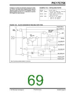
Example 10-2 shows an instruction sequence to initial-
ize PORTB. The Bank Select Register (BSR) must be
selected to Bank 0 for the port to be initialized. The fol-
lowing example uses the MOVLBinstruction to load the
BSR register for bank selection.
EXAMPLE 10-2: INITIALIZING PORTB
MOVLB
CLRF
0
; Select Bank 0
PORTB ; Initialize PORTB by clearing
output data latches
; Value used to initialize
data direction
; Set RB<3:0> as inputs
;
MOVLW 0xCF
MOVWF DDRB
;
;
;
RB<5:4> as outputs
RB<7:6> as inputs
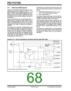
FIGURE 10-6: BLOCK DIAGRAM OF RB3:RB2 PORT PINS
Peripheral Data in
(PORTA<7>)
RBPU
Weak
Pull-Up
Match Signal
from other
port pins
RBIF
Port
Input Latch
Data Bus
RD_DDRB (Q2)
RD_PORTB (Q2)
D
OE
Q
WR_DDRB (Q4)
WR_PORTB (Q4)
CK
R
D
Port
Q
Data
CK
Peripheral_output
Peripheral_enable
Note: I/O pins have protection diodes to VDD and Vss.
1997 Microchip Technology Inc.
Preliminary
DS30264A-page 69

 MICROCHIP [ MICROCHIP ]