PIC17C75X
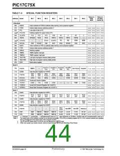
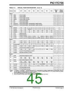
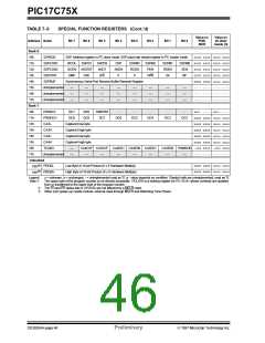
TABLE 7-3:
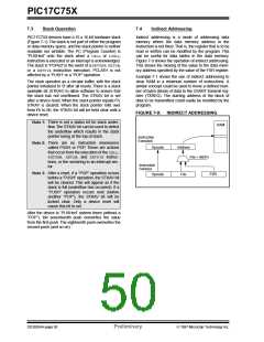
SPECIAL FUNCTION REGISTERS (Cont.’d)
Value on
POR,
BOR
Value on
all other
resets (3)
Address Name
Bit 7
Bit 6
Bit 5
Bit 4
Bit 3
Bit 2
Bit 1
Bit 0
Bank 6:
10h
11h
12h
13h
14h
15h
16h
17h
Bank 7:
10h
11h
12h
13h
14h
15h
16h
17h
SSPADD
SSP Address register in I2C slave mode. SSP baud rate reload register in I2C master mode.
0000 0000 0000 0000
SSPCON1
WCOL
GCEN
SMP
SSPOV
AKSTAT
CKE
SSPEN
AKDT
D/A
CKP
AKEN
P
SSPM3
RCEN
S
SSPM2
PEN
SSPM1
RSEN
UA
SSPM0 0000 0000 0000 0000
SSPCON2
SEN
BF
0000 0000 0000 0000
0000 0000 0000 0000
xxxx xxxx uuuu uuuu
---- ---- ---- ----
---- ---- ---- ----
---- ---- ---- ----
SSPSTAT
R/W
SSPBUF
Synchronous Serial Port Receive Buffer/Transmit Register
Unimplemented
Unimplemented
Unimplemented
—
—
—
—
—
—
—
—
—
—
—
—
—
—
—
—
—
—
—
—
—
—
—
—
PW3DCL
PW3DCH
CA3L
DC1
DC9
DC0
DC8
TM2PW3
DC7
-
-
-
-
-
xx0- ---- uu0- ----
xxxx xxxx uuuu uuuu
xxxx xxxx uuuu uuuu
xxxx xxxx uuuu uuuu
xxxx xxxx uuuu uuuu
xxxx xxxx uuuu uuuu
DC6
DC5
DC4
DC3
DC2
Capture3 low byte
Capture3 high byte
Capture4 low byte
Capture4 high byte
CA3H
CA4L
CA4H
TCON3
Unimplemented
—
—
CA4OVF CA3OVF
CA4ED1 CA4ED0 CA3ED1
CA3ED0 PWM3ON -000 0000 -000 0000
—
—
—
—
—
—
—
---- ---- ---- ----
Unbanked
18h(5)
19h(5)
xxxx xxxx uuuu uuuu
xxxx xxxx uuuu uuuu
PRODL
PRODH
Low Byte of 16-bit Product (8 x 8 Hardware Multiply)
High Byte of 16-bit Product (8 x 8 Hardware Multiply)
Legend:
Note 1:
x = unknown, u = unchanged, - = unimplemented read as '0', q - value depends on condition. Shaded cells are unimplemented, read as '0'.
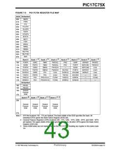
The upper byte of the program counter is not directly accessible. PCLATH is a holding register for PC<15:8> whose contents are updated
from or transferred to the upper byte of the program counter.
2: The TO and PD status bits in CPUSTA are not affected by a MCLR reset.
3: Other (non power-up) resets include: external reset through MCLR and Watchdog Timer Reset.
DS30264A-page 46
Preliminary
1997 Microchip Technology Inc.

 MICROCHIP [ MICROCHIP ]