PIC17C75X
7.2.2.2
CPU STATUS REGISTER (CPUSTA)
The POR bit allows the differentiation between a
Power-on Reset, external MCLR reset, or a WDT
Reset. The BOR bit indicates if a Brown-out Reset
occured.
The CPUSTA register contains the status and control
bits for the CPU. This register has a bit that is used to
globally enable/disable interrupts. If only a specific
interrupt is desired to be enabled/disabled, please refer
to the INTerrupt STAtus (INTSTA) register and the
Peripheral Interrupt Enable (PIE) registers. The
CPUSTA register also indicates if the stack is available
and contains the Power-down (PD) and Time-out (TO)
bits. The TO, PD, and STKAV bits are not writable.
These bits are set and cleared according to device
logic. Therefore, the result of an instruction with the
CPUSTA register as destination may be different than
intended.
Note 1: The BOR status bit is a don’t care and is
not necessarily predictable if the
brown-out circuit is disabled (when the
BODEN bit in the Configuration word is
programmed).
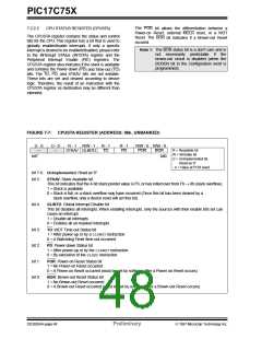
FIGURE 7-7: CPUSTA REGISTER (ADDRESS: 06h, UNBANKED)
U - 0
—
U - 0
—
R - 1
STKAV GLINTD
R/W - 1
R - 1
TO
R - 1
PD
R/W - 0 R/W - 0
POR BOR
bit0
R = Readable bit
W = Writable bit
U = Unimplemented bit,
Read as ‘0’
bit7
- n = Value at POR reset
bit 7-6: Unimplemented: Read as '0'
bit 5:
STKAV: Stack Available bit
This bit indicates that the 4-bit stack pointer value is Fh, or has rolled over from Fh → 0h (stack overflow).
1 = Stack is available
0 = Stack is full, or a stack overflow may have occurred (Once this bit has been cleared by a
stack overflow, only a device reset will set this bit)
bit 4:
GLINTD: Global Interrupt Disable bit
This bit disables all interrupts. When enabling interrupts, only the sources with their enable bits set can
cause an interrupt.
1 = Disable all interrupts
0 = Enables all un-masked interrupts
bit 3:
bit 2:
bit 1:
bit 0:
TO: WDT Time-out Status bit
1 = After power-up or by a CLRWDTinstruction
0 = A Watchdog Timer time-out occurred
PD: Power-down Status bit
1 = After power-up or by the CLRWDTinstruction
0 = By execution of the SLEEPinstruction
POR: Power-on Reset Status bit
1 = No Power-on Reset occurred
0 = A Power-on Reset occurred (must be set by software after a Power-on Reset occurs)
BOR: Brown-out Reset Status bit
1 = No Brown-out Reset occurred
0 = A Brown-out Reset occurred (must be set by software after a Brown-out Reset occurs)
DS30264A-page 48
Preliminary
1997 Microchip Technology Inc.

 MICROCHIP [ MICROCHIP ]