PIC17C4X
21.5
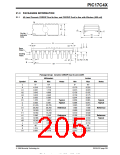
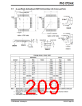
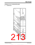
44-Lead Plastic Surface Mount (TQFP 10x10 mm Body 1.0/0.10 mm Lead Form)
D
D1
1.0ø (0.039ø) Ref.
11°/13°(4x)
0° Min
Pin#1
2
Pin#1
2
E
E1
Θ
11°/13°(4x)
Detail B
e
3.0ø (0.118ø) Ref.
R 1 0.08 Min
R 0.08/0.20
Option 1 (TOP side)
Option 2 (TOP side)
Gage Plane
0.250
A1
Base Metal
Lead Finish
b
A2
A
S
0.20
Min
L
L
c
c1
L1
Detail A
Detail B
1.00 Ref
1.00 Ref.
b1
Detail A
Detail B
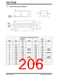
Package Group: Plastic TQFP
Millimeters
Max
Inches
Max
Symbol
Min
Notes
Min
Notes
A
A1
A2
D
1.00
0.05
0.95
11.75
9.90
11.75
9.90
0.45
1.20
0.15
0.039
0.002
0.037
0.463
0.390
0.463
0.390
0.018
0.047
0.006
0.041
0.482
0.398
0.482
0.398
0.030
1.05
12.25
10.10
12.25
10.10
0.75
D1
E
E1
L
e
0.80 BSC
0.031 BSC
b
0.30
0.30
0.09
0.09
44
0.45
0.40
0.20
0.16
44
0.012
0.012
0.004
0.004
44
0.018
0.016
0.008
0.006
44
b1
c
c1
N
Θ
0°
7°
0°
7°
Note 1: Dimensions D1 and E1 do not include mold protrusion. Allowable mold protrusion is 0.25m/m (0.010”) per
side. D1 and E1 dimensions including mold mismatch.
2: Dimension “b” does not include Dambar protrusion, allowable Dambar protrusion shall be 0.08m/m
(0.003”)max.
3: This outline conforms to JEDEC MS-026.
1996 Microchip Technology Inc.
DS30412C-page 209

 MICROCHIP [ MICROCHIP ]