PIC16F913/914/916/917/946
11.1 PLVD Operation
11.4 Stable Reference Indication
To setup the PLVD for operation, the following steps
must be taken:
When the PLVD module is enabled, the reference volt-
age must be allowed to stabilize before the PLVD will
provide a valid result. Refer to Section 19.0 “Electri-
cal Specifications”, Table 19-13, for the stabilization
time.
• Enable the module by setting the LVDEN bit of the
LVDCON register.
• Configure the trip point by setting the LVDL<2:0>
bits of the LVDCON register.
When the HFINTOSC is running, the IRVST bit of the
LVDCON register indicates the stability of the voltage
reference. The voltage reference is stable when the
IRVST bit is set.
• Wait for the reference voltage to become stable.
Refer to Section 11.4 “Stable Reference
Indication”.
• Clear the LVDIF bit of the PIR2 register.
11.5 Operation During Sleep
The LVDIF bit will be set when VDD falls below the
PLVD trip point. The LVDIF bit remains set until cleared
by software. Refer to Figure 11-2.
To wake from Sleep, set the LVDIE bit of the PIE2
register and the PEIE bit of the INTCON register. When
the LVDIE and PEIE bits are set, the device will wake
from Sleep and execute the next instruction. If the GIE
bit is also set, the program will call the Interrupt Service
Routine upon completion of the first instruction after
waking from Sleep.
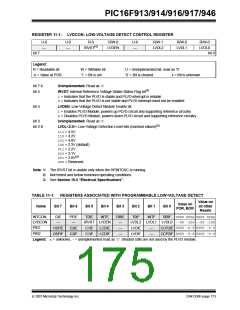
11.2 Programmable Trip Point
The PLVD trip point is selectable from one of eight
voltage levels. The LVDL bits of the LVDCON register
select the trip point. Refer to Register 11-1 for the
available PLVD trip points.
11.3 Interrupt on Falling VDD
When VDD falls below the PLVD trip point, the falling
edge detector will set the LVDIF bit. See Figure 11-2.
An interrupt will be generated if the following bits are
also set:
• GIE and PEIE bits of the INTCON register
• LVDIE bit of the PIE2 register
The LVDIF bit must be cleared by software. An interrupt
can be generated from a simulated PLVD event when
the LVDIF bit is set by software.
DS41250F-page 172
© 2007 Microchip Technology Inc.

 MICROCHIP [ MICROCHIP ]