PIC16F87/88
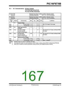
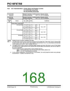
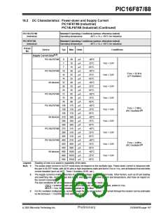
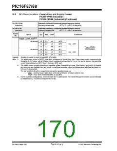
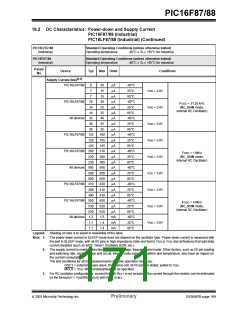
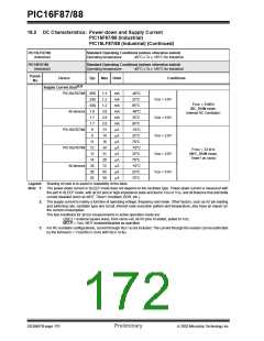
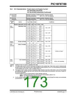
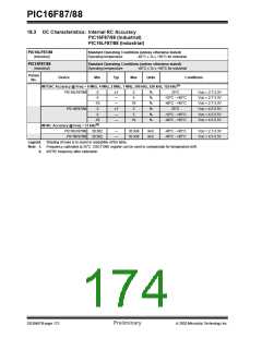
18.2 DC Characteristics: Power-down and Supply Current
PIC16F87/88 (Industrial)
PIC16LF87/88 (Industrial) (Continued)
PIC16LF87/88
Standard Operating Conditions (unless otherwise stated)
Operating temperature -40°C ≤ TA ≤ +85°C for industrial
(Industrial)
PIC16F87/88
Standard Operating Conditions (unless otherwise stated)
(Industrial)
Operating temperature
-40°C ≤ TA ≤ +85°C for industrial
Param
No.
Device
Typ
Max Units
Conditions
(2,3)
Supply Current (IDD)
PIC16LF87/88
PIC16LF87/88
All devices
8
20
15
µA
µA
µA
µA
µA
µA
µA
µA
µA
µA
µA
µA
µA
µA
µA
µA
µA
µA
µA
µA
µA
µA
µA
µA
mA
mA
mA
-40°C
7
25°C
85°C
-40°C
25°C
85°C
-40°C
25°C
85°C
-40°C
25°C
85°C
-40°C
25°C
85°C
-40°C
25°C
85°C
-40°C
25°C
85°C
-40°C
25°C
85°C
-40°C
25°C
85°C
VDD = 2.0V
VDD = 3.0V
VDD = 5.0V
VDD = 2.0V
VDD = 3.0V
VDD = 5.0V
VDD = 2.0V
VDD = 3.0V
VDD = 5.0V
7
15
16
14
14
32
29
29
30
FOSC = 31.25 kHz
(RC_RUN mode,
Internal RC Oscillator)
25
25
40
35
35
PIC16LF87/88 132
160
155
155
310
300
300
690
650
650
420
410
410
650
620
620
1.5
1.4
1.4
126
126
PIC16LF87/88 260
FOSC = 1 MHz
(RC_RUN mode,
Internal RC Oscillator)
230
230
All devices 560
500
500
PIC16LF87/88 310
300
300
PIC16LF87/88 550
FOSC = 4 MHz
(RC_RUN mode,
Internal RC Oscillator)
530
530
All devices 1.2
1.1
1.1
Legend:
Shading of rows is to assist in readability of the table.
Note 1: The power-down current in SLEEP mode does not depend on the oscillator type. Power-down current is measured with
the part in SLEEP mode, with all I/O pins in high-impedance state and tied to VDD or VSS, and all features that add delta
current disabled (such as WDT, Timer1 Oscillator, BOR, etc.).
2: The supply current is mainly a function of operating voltage, frequency and mode. Other factors, such as I/O pin loading
and switching rate, oscillator type and circuit, internal code execution pattern and temperature, also have an impact on
the current consumption.
The test conditions for all IDD measurements in active operation mode are:
OSC1 = external square wave, from rail-to-rail; all I/O pins tri-stated, pulled to VDD;
MCLR = VDD; WDT enabled/disabled as specified.
3: For RC oscillator configurations, current through REXT is not included. The current through the resistor can be estimated
by the formula Ir = VDD/2REXT (mA) with REXT in kΩ.
2003 Microchip Technology Inc.
Preliminary
DS30487B-page 169

 MICROCHIP [ MICROCHIP ]