PIC16F87/88
supply voltage (also referred to as CVRSRC) comes
directly from VDD. It should be noted, however, that the
voltage at the top of the ladder is CVRSRC – VSAT,
where VSAT is the saturation voltage of the power
switch transistor. This reference will only be as
accurate as the values of CVRSRC and VSAT.
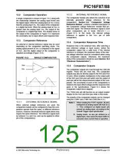
14.0 COMPARATOR VOLTAGE
REFERENCE MODULE
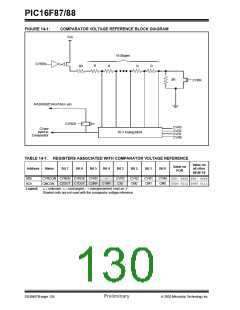
The Comparator Voltage Reference Generator is a 16-
tap resistor ladder network that provides a fixed voltage
reference when the comparators are in mode ‘110’. A
programmable register controls the function of the ref-
erence generator. Register 14-1 lists the bit functions of
the CVRCON register.
The output of the reference generator may be con-
nected to the RA2/AN2/CVREF/VREF- pin. This can be
used as a simple D/A function by the user, if a very
high-impedance load is used. The primary purpose of
this function is to provide a test path for testing the
reference generator function.
As shown in Figure 14-1, the resistor ladder is seg-
mented to provide two ranges of CVREF values and has
a power-down function to conserve power when the
reference is not being used. The comparator reference
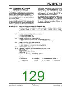
REGISTER 14-1: CVRCON CONTROL REGISTER (ADDRESS 9Dh)
R/W-0
R/W-0
R/W-0
CVRR
U-0
—
R/W-0
CVR3
R/W-0
CVR2
R/W-0
CVR1
R/W-0
CVR0
CVREN
CVROE
bit 7
bit 0
bit 7
bit 6
bit 5
CVREN: Comparator Voltage Reference Enable bit
1= CVREF circuit powered on
0= CVREF circuit powered down
CVROE: Comparator VREF Output Enable bit
1= CVREF voltage level is output on the RA2/AN2/CVREF/VREF- pin
0= CVREF voltage level is disconnected from the RA2/AN2/CVREF/VREF- pin
CVRR: Comparator VREF Range Selection bit
1= 0.00 CVRSRC to 0.75 CVRSRC with CVRSRC/24 step size
0= 0.25 CVRSRC to 0.75 CVRSRC with CVRSRC/32 step size
bit 4
Unimplemented: Read as ‘0’
bit 3-0
CVR<3:0>: Comparator VREF Value Selection 0 ≤ VR3:VR0 ≤ 15 bits
When CVRR = 1:
CVREF = (VR<3:0>/24) • (CVRSRC)
When CVRR = 0:
CVREF = 1/4 • (CVRSRC) + (VR3:VR0/32) • (CVRSRC)
Legend:
R = Readable bit
-n = Value at POR
W = Writable bit
‘1’ = Bit is set
U = Unimplemented bit, read as ‘0’
‘0’ = Bit is cleared x = Bit is unknown
2003 Microchip Technology Inc.
Preliminary
DS30487B-page 127

 MICROCHIP [ MICROCHIP ]