PIC16F87/88
13.7 Comparator Operation During
SLEEP
13.9 Analog Input Connection
Considerations
When a comparator is active and the device is placed
in SLEEP mode, the comparator remains active and
the interrupt is functional, if enabled. This interrupt will
wake-up the device from SLEEP mode when enabled.
While the comparator is powered up, higher SLEEP
currents than shown in the power-down current
specification will occur. Each operational comparator
will consume additional current, as shown in the com-
parator specifications. To minimize power consumption
while in SLEEP mode, turn off the comparators,
CM<2:0> = 111, before entering SLEEP. If the device
wakes up from SLEEP, the contents of the CMCON
register are not affected.
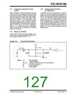
A simplified circuit for an analog input is shown in
Figure 13-4. Since the analog pins are connected to a
digital output, they have reverse biased diodes to VDD
and VSS. The analog input, therefore, must be between
VSS and VDD. If the input voltage deviates from this
range by more than 0.6V in either direction, one of the
diodes is forward biased and a latch-up condition may
occur. A maximum source impedance of 10 kΩ is rec-
ommended for the analog sources. Any external com-
ponent connected to an analog input pin, such as a
capacitor or a Zener diode, should have very little
leakage current.
13.8 Effects of a RESET
A device RESET forces the CMCON register to its
RESET state, causing the comparator module to be in
the Comparator Off mode, CM<2:0> = 111.
FIGURE 13-4:
ANALOG INPUT MODEL
VDD
VT = 0.6V
RIC
RS < 10K
AIN
ILEAKAGE
±500 nA
CPIN
5 pF
VA
VT = 0.6V
VSS
Legend: CPIN
=
Input Capacitance
VT
= Threshold Voltage
ILEAKAGE = Leakage Current at the pin due to various junctions
RIC
RS
VA
=
=
=
Interconnect Resistance
Source Impedance
Analog Voltage
2003 Microchip Technology Inc.
Preliminary
DS30487B-page 125

 MICROCHIP [ MICROCHIP ]