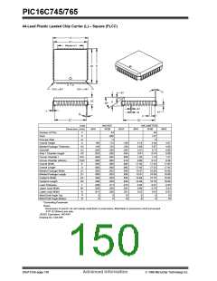
PIC16C745/765
INDEX
C
C bit ................................................................................... 22
Capture/Compare/PWM
A
A/D
Capture
ADCON0 Register ..................................................... 89
Block Diagram ................................................... 53
CCP1CON Register .......................................... 52
CCP1IF ............................................................. 53
Mode ................................................................. 53
Prescaler ........................................................... 53
CCP Timer Resources .............................................. 51
Compare
Analog Input Model Block Diagram............................. 92
Analog-to-Digital Converter......................................... 89
Block Diagram ........................................................... 91
Configuring Analog Port Pins .................................... 93
Configuring the Interrupt ............................................ 91
Configuring the Module ............................................. 91
Conversion Clock ...................................................... 93
Conversions .............................................................. 93
Converter Characteristics ........................................ 138
Effects of a Reset ...................................................... 94
Faster Conversion - Lower Resolution Tradeoff ........ 93
Internal Sampling Switch (Rss) Impedance .............. 92
Operation During Sleep ............................................. 94
Sampling Requirements ............................................ 92
Source Impedance .................................................... 92
Timing Diagram ....................................................... 139
Using the CCP Trigger .............................................. 94
Absolute Maximum Ratings ............................................. 123
ADRES Register ......................................................... 17, 89
Application Notes
Block Diagram ................................................... 54
Mode ................................................................. 54
Software Interrupt Mode ................................... 54
Special Event Trigger ........................................ 54
Special Trigger Output of CCP1 ....................... 54
Special Trigger Output of CCP2 ....................... 54
Interaction of Two CCP Modules.................... 51
Section ...................................................................... 51
Special Event Trigger and A/D Conversions ............. 54
Capture/Compare/PWM (CCP)
PWM Block Diagram ................................................. 54
PWM Mode ............................................................... 54
Timing Diagram ....................................................... 135
CCP1CON ......................................................................... 19
CCP2CON ......................................................................... 19
CCPR1H Register ............................................... 17, 19, 51
CCPR1L Register ....................................................... 19, 51
CCPR2H Register ...................................................... 17, 19
CCPR2L Register ....................................................... 17, 19
Clocking Scheme .............................................................. 13
Code Examples
AN552, Implementing Wake-up on Key Strokes Using
PIC16CXXX ............................................................... 33
AN556, Table Reading Using PIC16CXX ................. 29
AN607, Power-up Trouble Shooting .......................... 99
Architecture
Overview ..................................................................... 9
Assembler
MPASM Assembler ................................................. 117
Call of a Subroutine in Page 1 from Page 0 .............. 29
Changing Prescaler (Timer0 to WDT) ....................... 44
Indirect Addressing ................................................... 30
Initializing PORTA ..................................................... 31
Code Protection ....................................................... 95, 108
Computed GOTO .............................................................. 29
Configuration Bits .............................................................. 95
Control ............................................................................... 60
CREN bit ........................................................................... 76
CS pin ............................................................................... 40
B
Baud Rate Formula ........................................................... 77
Block Diagrams
A/D ............................................................................ 91
Analog Input Model ................................................... 92
Capture ...................................................................... 53
Compare .................................................................... 54
On-Chip Reset Circuit ............................................... 98
PORTC ...................................................................... 35
PORTD (In I/O Port Mode) ........................................ 37
PORTD and PORTE as a Parallel Slave Port ........... 40
PORTE (In I/O Port Mode) ........................................ 38
PWM .......................................................................... 54
RA4/T0CKI Pin .......................................................... 31
RB Port Pins .............................................................. 33
RB Port Pins .............................................................. 33
Timer0/WDT Prescaler .............................................. 43
Timer2 ....................................................................... 49
USART Receive ........................................................ 81
USART Transmit ....................................................... 79
Watchdog Timer ...................................................... 106
BOR bit .............................................................................. 99
BRGH bit ........................................................................... 77
Brown-out Reset (BOR)
D
DC bit ................................................................................ 22
DC Characteristics ........................................ 125, 126, 127
Development Support ................................................ 5, 117
Direct Addressing .............................................................. 30
E
EC Oscillator ................................................................... 100
Electrical Characteristics ................................................. 123
Endpoint ............................................................................ 70
Errata .................................................................................. 3
Error .................................................................................. 63
F
FERR bit ............................................................................ 76
FSR Register ................................................ 17, 18, 20, 30
G
Timing Diagram ....................................................... 133
Buffer Descriptor Table ...................................................... 68
General Description ............................................................ 5
GIE bit ............................................................................. 103
1999 Microchip Technology Inc.
Advanced Information
DS41124A-page 151

 MICROCHIP [ MICROCHIP ]