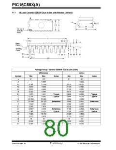
PIC16C55X(A)
Plastic Dual In-Line Family
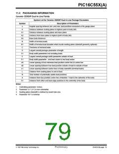
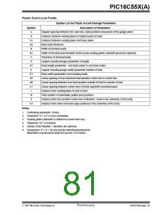
Symbol
Symbol List for Plastic In-Line Package Parameters
Description of Parameters
α
Angular spacing between min. and max. lead positions measured at the gauge plane
Distance between seating plane to highest point of body
Distance between seating plane and base plane
A
A1
A2
B
Base body thickness
Width of terminal leads
B1
C
Width of terminal lead shoulder which locate seating plane (standoff geometry optional)
Thickness of terminal leads
D
Largest overall package parameter of length
D1
E
Body length parameter - end lead center to end lead center
Largest overall package width parameter outside of lead
Body width parameters not including leads
E1
eA
eB
e1
L
Linear spacing of true minimum lead position center line to center line
Linear spacing between true lead position outside of lead to outside of lead
Linear spacing between center lines of body standoffs (terminal leads)
Distance from seating plane to end of lead
N
Total number of potentially usable lead positions
S
Distance from true position center line of Number 1 lead to the extremity of the body
Distance from other end lead edge positions to the extremity of the body
S1
Notes:
1. Controlling parameter: inches.
2. Parameter “e1” (“e”) is non-cumulative.
3. Seating plane (standoff) is defined by board hole size.
4. Parameter “B1” is nominal.
5. Details of pin Number 1 identifier are optional.
6. Parameters “D + E1” do not include mold flash/protrusions.
Mold flash or protrusions shall not exceed .010 inches.
1997 Microchip Technology Inc.
Preliminary
DS40143B-page 81

 MICROCHIP [ MICROCHIP ]