PIC16C55X(A)
on MCLR reset during SLEEP.They are not affected by
a WDT wake-up, since this is viewed as the resumption
of normal operation. TO and PD bits are set or cleared
differently in different reset situations as indicated in
Table 7-4.These bits are used in software to determine
the nature of the reset. See Table 7-6 for a full descrip-
tion of reset states of all registers.
7.3
Reset
The PIC16C55X(A) differentiates between various
kinds of reset:
a) Power-on reset (POR)
b) MCLR reset during normal operation
c) MCLR reset during SLEEP
d) WDT reset (normal operation)
e) WDT wake-up (SLEEP)
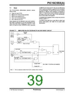
A simplified block diagram of the on-chip reset circuit is
shown in Figure 7-7.
The MCLR reset path has a noise filter to detect and
ignore small pulses. See Table 10-4 for pulse width
specification.
Some registers are not affected in any reset condition;
their status is unknown on POR and unchanged in any
other reset. Most other registers are reset to a “reset
state” on Power-on reset, on MCLR or WDT reset and
FIGURE 7-7: SIMPLIFIED BLOCK DIAGRAM OF ON-CHIP RESET CIRCUIT
External
Reset
MCLR/
VPP Pin
SLEEP
WDT
WDT
Module
Time-out
Reset
VDD rise
detect
Power-on Reset
VDD
S
R
OST/PWRT
OST
Chip_Reset
10-bit Ripple-counter
Q
OSC1/
CLKIN
Pin
PWRT
(1)
On-chip
RC OSC
10-bit Ripple-counter
Enable PWRT
Enable OST
See Table 7-3 for time-out situations.
Note 1: This is a separate oscillator from the RC oscillator of the CLKIN pin.
1997 Microchip Technology Inc.
Preliminary
DS40143B-page 39

 MICROCHIP [ MICROCHIP ]