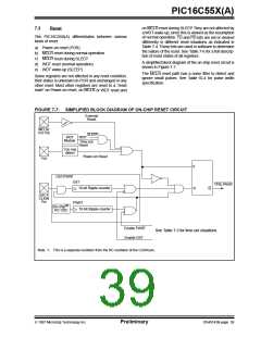
PIC16C55X(A)
7.2
Oscillator Configurations
TABLE 7-1:
CAPACITOR SELECTION
FOR CERAMIC RESONATORS
(PRELIMINARY)
7.2.1
OSCILLATOR TYPES
The PIC16C55X(A) can be operated in four different
oscillator options. The user can program two
configuration bits (FOSC1 and FOSC0) to select one of
these four modes:
Ranges Characterized:
Mode
Freq
OSC1(C1)
OSC2(C2)
XT
455 kHz
2.0 MHz
4.0 MHz
22 - 100 pF
15 - 68 pF
15 - 68 pF
22 - 100 pF
15 - 68 pF
15 - 68 pF
• LP
• XT
• HS
• RC
Low Power Crystal
Crystal/Resonator
High Speed Crystal/Resonator
Resistor/Capacitor
HS
8.0 MHz
10 - 68 pF
10 - 22 pF
10 - 68 pF
10 - 22 pF
16.0 MHz
Higher capacitance increases the stability of the oscillator
but also increases the start-up time. These values are for
design guidance only. Since each resonator has its own
characteristics, the user should consult the resonator man-
ufacturer for appropriate values of external components.
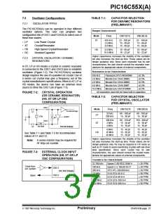
7.2.2
CRYSTAL OSCILLATOR / CERAMIC
RESONATORS
In XT, LP or HS modes a crystal or ceramic resonator
is connected to the OSC1 and OSC2 pins to establish
oscillation (Figure 7-2). The PIC16C55X(A) oscillator
design requires the use of a parallel cut crystal. Use of
a series cut crystal may give a frequency out of the
crystal manufacturers specifications.When in XT, LP or
HS modes, the device can have an external clock
source to drive the OSC1 pin (Figure 7-3).
Resonators to be Characterized:
455 kHz
2.0 MHz
4.0 MHz
8.0 MHz
16.0 MHz
Panasonic EFO-A455K04B
Murata Erie CSA2.00MG
Murata Erie CSA4.00MG
Murata Erie CSA8.00MT
Murata Erie CSA16.00MX
±0.3%
±0.5%
±0.5%
±0.5%
±0.5%
All resonators used did not have built-in capacitors.
FIGURE 7-2: CRYSTAL OPERATION
(OR CERAMIC RESONATOR)
(HS, XT OR LP OSC
TABLE 7-2:
CAPACITOR SELECTION
FOR CRYSTAL OSCILLATOR
(PRELIMINARY)
CONFIGURATION)
OSC1
Mode
Freq
OSC1(C1)
OSC2(C2)
To internal logic
C1
32 kHz
200 kHz
68 - 100 pF
15 - 30 pF
68 - 100 pF
15 - 30 pF
LP
XTAL
RS
SLEEP
RF
100 kHz
2 MHz
4 MHz
68 - 150 pF
15 - 30 pF
15 - 30 pF
150 - 200 pF
15 - 30 pF
15 - 30 pF
OSC2
XT
HS
see Note
C2
PIC16C55X(A)
8 MHz
10 MHz
20 MHz
15 - 30 pF
15 - 30 pF
15 - 30 pF
15 - 30 pF
15 - 30 pF
15 - 30 pF
See Table 7-1 and Table 7-2 for recommended
values of C1 and C2.
Higher capacitance increases the stability of the oscillator
but also increases the start-up time. These values are for
design guidance only. Rs may be required in HS mode as
well as XT mode to avoid overdriving crystals with low drive
level specification. Since each crystal has its own
characteristics, the user should consult the crystal manu-
facturer for appropriate values of external components.
Note: A series resistor may be required for
AT strip cut crystals.
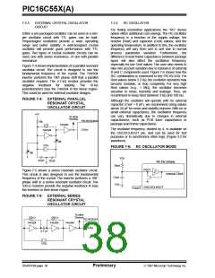
FIGURE 7-3: EXTERNAL CLOCK INPUT
OPERATION (HS, XT OR LP
OSC CONFIGURATION)
Crystals to be Characterized:
32.768 kHz
100 kHz
Epson C-001R32.768K-A
Epson C-2 100.00 KC-P
STD XTL 200.000 kHz
ECS ECS-20-S-2
± 20 PPM
± 20 PPM
± 20 PPM
± 50 PPM
± 50 PPM
± 50 PPM
± 50 PPM
Clock from
ext. system
OSC1
200 kHz
PIC16C55X(A)
2.0 MHz
4.0 MHz
10.0 MHz
20.0 MHz
OSC2
Open
ECS ECS-40-S-4
ECS ECS-100-S-4
ECS ECS-200-S-4
1997 Microchip Technology Inc.
Preliminary
DS40143B-page 37

 MICROCHIP [ MICROCHIP ]