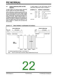
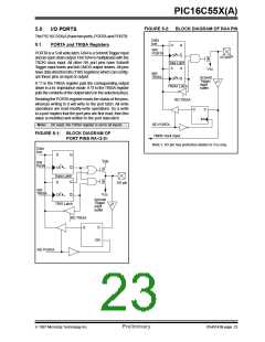
PIC16C55X(A)
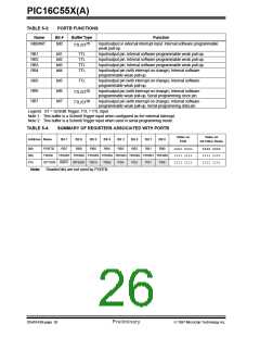
TABLE 5-3:
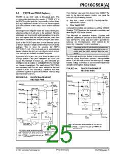
PORTB FUNCTIONS
Name
Bit #
Buffer Type
Function
(1)
RB0/INT
bit0
Input/output or external interrupt input. Internal software programmable
weak pull-up.
TTL/ST
RB1
RB2
RB3
RB4
bit1
bit2
bit3
bit4
TTL
TTL
TTL
TTL
Input/output pin. Internal software programmable weak pull-up.
Input/output pin. Internal software programmable weak pull-up.
Input/output pin. Internal software programmable weak pull-up.
Input/output pin (with interrupt on change). Internal software
programmable weak pull-up.
RB5
RB6
RB7
bit5
bit6
bit7
TTL
Input/output pin (with interrupt on change). Internal software
programmable weak pull-up.
(2)
Input/output pin (with interrupt on change). Internal software
programmable weak pull-up. Serial programming clock pin.
TTL/ST
(2)
Input/output pin (with interrupt on change). Internal software
programmable weak pull-up. Serial programming data pin.
TTL/ST
Legend: ST = Schmitt Trigger, TTL = TTL input
Note 1: This buffer is a Schmitt Trigger input when configured as the external interrupt.
Note 2: This buffer is a Schmitt Trigger input when used in serial programming mode.
TABLE 5-4:
SUMMARY OF REGISTERS ASSOCIATED WITH PORTB
Value on
POR
Value on
All Other Rests
Address Name
Bit 7
Bit 6
Bit 5
Bit 4
Bit 3
Bit 2
Bit 1
Bit 0
06h
86h
81h
PORTB
TRISB
RB7
RB6
RB5
RB4
RB3
RB2
RB1
RB0
uuuu uuuu
1111 1111
1111 1111
xxxx xxxx
1111 1111
1111 1111
TRISB7 TRISB6 TRISB5 TRISB4 TRISB3 TRISB2 TRISB1 TRISB0
T0SE PSA PS2 PS1 PS0
OPTION RBPU INTEDG T0CS
Note: Shaded bits are not used by PORTB.
DS40143B-page 26
Preliminary
1997 Microchip Technology Inc.

 MICROCHIP [ MICROCHIP ]