PIC16C55X(A)
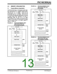
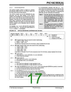
FIGURE 4-2: PROGRAM MEMORY MAP
AND STACK FOR THE
4.0
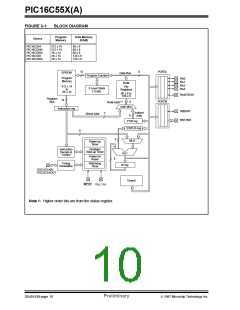
MEMORY ORGANIZATION
4.1
Program Memory Organization
PIC16C556A
The PIC16C55X(A) has a 13-bit program counter capa-
ble of addressing an 8K x 14 program memory space.
Only the first 512 x 14 (0000h - 01FFh) for the
PIC16C554(A), 1K x 14 (0000h - 03FFh) for the
PIC16C556A and 2K x 14 (0000h - 07FFh) for the
PIC16C558(A) are physically implemented. Accessing
a location above these boundaries will cause a
PC<12:0>
CALL, RETURN
RETFIE, RETLW
13
Stack Level 1
Stack Level 2
wrap-around within the first 512
x 14 space
PIC16C554(A) or 1K x 14 space PIC16C556A or 2K x
14 space PIC16C558(A). The reset vector is at 0000h
and the interrupt vector is at 0004h (Figure 4-1,
Figure 4-2, Figure 4-3).
Stack Level 8
Reset Vector
000h
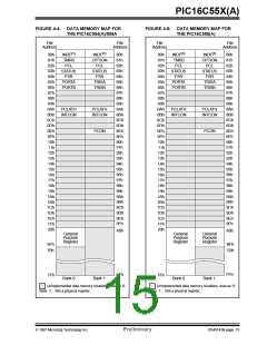
FIGURE 4-1: PROGRAM MEMORY MAP
AND STACK FOR THE
Interrupt Vector
0004
0005
PIC16C554/PIC6C554A
PC<12:0>
On-chip Program
Memory
CALL, RETURN
RETFIE, RETLW
13
03FFh
0400h
Stack Level 1
Stack Level 2
1FFFh
Stack Level 8
FIGURE 4-3: PROGRAM MEMORY MAP
AND STACK FOR THE
Reset Vector
PIC16C558/PIC16C558A
000h
PC<12:0>
CALL, RETURN
RETFIE, RETLW
13
Interrupt Vector
0004
0005
Stack Level 1
Stack Level 2
On-chip Program
Memory
Stack Level 8
01FFh
0200h
Reset Vector
000h
1FFFh
Interrupt Vector
0004
0005
On-chip Program
Memory
07FFh
0800h
1FFFh
1997 Microchip Technology Inc.
Preliminary
DS40143B-page 13

 MICROCHIP [ MICROCHIP ]