PIC16F/LF1946/47
23.5.2 SLAVE RECEPTION
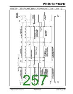
23.5.2.2 7-bit Reception with AHEN and DHEN
When the R/W bit of a matching received address byte
is clear, the R/W bit of the SSPxSTAT register is
cleared. The received address is loaded into the
SSPxBUF register and acknowledged.
Slave device reception with AHEN and DHEN set
operate the same as without these options with extra
interrupts and clock stretching added after the 8th fall-
ing edge of SCLx. These additional interrupts allow the
slave software to decide whether it wants to ACK the
receive address or data byte, rather than the hard-
ware. This functionality adds support for PMBus™ that
was not present on previous versions of this module.
When the overflow condition exists for a received
address, then not Acknowledge is given. An overflow
condition is defined as either bit BF bit of the
SSPxSTAT register is set, or bit SSPxOV bit of the
SSPxCON1 register is set. The BOEN bit of the
SSPxCON3 register modifies this operation. For more
information see Register 23-4.
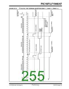
This list describes the steps that need to be taken by
slave software to use these options for I2C communi-
cation. Figure 23-15 displays a module using both
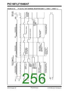
address and data holding. Figure 23-16 includes the
operation with the SEN bit of the SSPxCON2 register
set.
An MSSPx interrupt is generated for each transferred
data byte. Flag bit, SSPxIF, must be cleared by
software.
1. S bit of SSPxSTAT is set; SSPxIF is set if inter-
rupt on Start detect is enabled.
When the SEN bit of the SSPxCON2 register is set,
SCLx will be held low (clock stretch) following each
received byte. The clock must be released by setting
the CKP bit of the SSPxCON1 register, except
sometimes in 10-bit mode. See Section 23.2.3 “SPI
Master Mode” for more detail.
2. Matching address with R/W bit clear is clocked
in. SSPxIF is set and CKP cleared after the 8th
falling edge of SCLx.
3. Slave clears the SSPxIF.
4. Slave can look at the ACKTIM bit of the
SSPxCON3 register to determine if the SSPxIF
was after or before the ACK.
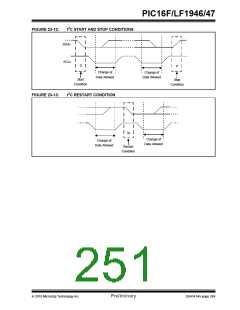
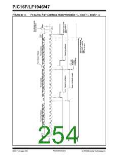
23.5.2.1 7-bit Addressing Reception
This section describes a standard sequence of events
for the MSSPx module configured as an I2C Slave in
7-bit Addressing mode. All decisions made by hard-
ware or software and their effect on reception.
Figure 23-13 and Figure 23-14 is used as a visual
reference for this description.
5. Slave reads the address value from SSPxBUF,
clearing the BF flag.
6. Slave sets ACK value clocked out to the master
by setting ACKDT.
7. Slave releases the clock by setting CKP.
This is a step by step process of what typically must
be done to accomplish I2C communication.
8. SSPxIF is set after an ACK, not after a NACK.
9. If SEN = 1 the slave hardware will stretch the
1. Start bit detected.
clock after the ACK.
2. S bit of SSPxSTAT is set; SSPxIF is set if inter-
rupt on Start detect is enabled.
10. Slave clears SSPxIF.
Note: SSPxIF is still set after the 9th falling edge of
SCLx even if there is no clock stretching and
BF has been cleared. Only if NACK is sent to
Master is SSPxIF not set
3. Matching address with R/W bit clear is received.
4. The slave pulls SDAx low sending an ACK to the
master, and sets SSPxIF bit.
5. Software clears the SSPxIF bit.
11. SSPxIF set and CKP cleared after 8th falling
edge of SCLx for a received data byte.
6. Software reads received address from
SSPxBUF clearing the BF flag.
12. Slave looks at ACKTIM bit of SSPxCON3 to
determine the source of the interrupt.
7. If SEN = 1; Slave software sets CKP bit to
release the SCLx line.
13. Slave reads the received data from SSPxBUF
clearing BF.
8. The master clocks out a data byte.
9. Slave drives SDAx low sending an ACK to the
master, and sets SSPxIF bit.
14. Steps 7-14 are the same for each received data
byte.
10. Software clears SSPxIF.
15. Communication is ended by either the slave
sending an ACK = 1, or the master sending a
Stop condition. If a Stop is sent and Interrupt on
Stop Detect is disabled, the slave will only know
by polling the P bit of the SSTSTAT register.
11. Software reads the received byte from
SSPxBUF clearing BF.
12. Steps 8-12 are repeated for all received bytes
from the Master.
13. Master sends Stop condition, setting P bit of
SSPxSTAT, and the bus goes idle.
2010 Microchip Technology Inc.
Preliminary
DS41414A-page 251

 MICROCHIP [ MICROCHIP ]