PIC16F/LF1946/47
The I2C interface supports the following modes and
features:
The PIC16F1947 has two MSSP modules, MSSP1 and
MSSP2, each module operating independently from
the other.
• Master mode
• Slave mode
• Byte NACKing (Slave mode)
• Limited Multi-master support
• 7-bit and 10-bit addressing
• Start and Stop interrupts
• Interrupt masking
Note 1: In devices with more than one MSSP
module, it is very important to pay close
attention to SSPxCONx register names.
SSP1CON1 and SSP1CON2 registers
control different operational aspects of the
same module, while SSP1CON1 and
SSP2CON1 control the same features for
two different modules.
• Clock stretching
• Bus collision detection
• General call address matching
• Address masking
2: Throughout this section, generic refer-
ences to an MSSP module in any of its
operating modes may be interpreted as
being equally applicable to MSSP1 or
MSSP2. Register names, module I/O sig-
nals, and bit names may use the generic
designator ‘x’ to indicate the use of a
numeral to distinguish a particular module
when required.
• Address Hold and Data Hold modes
• Selectable SDAx hold times
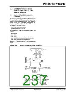
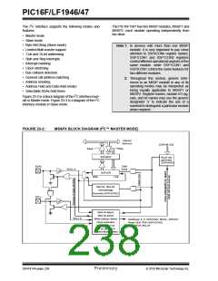
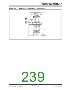
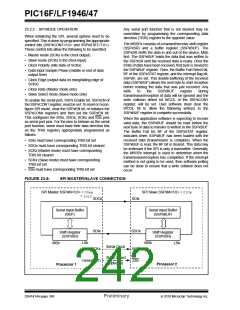
Figure 23-2 is a block diagram of the I2C interface mod-
ule in Master mode. Figure 23-3 is a diagram of the I2C
interface module in Slave mode.
FIGURE 23-2:
MSSPX BLOCK DIAGRAM (I2C™ MASTER MODE)
Internal
data bus
[SSPxM 3:0]
Read
Write
SSPxBUF
SSPxSR
Baud rate
generator
(SSPxADD)
SDAx
Shift
Clock
SDAx in
MSb
LSb
Start bit, Stop bit,
Acknowledge
Generate (SSPxCON2)
SCLx
Start bit detect,
Stop bit detect
SCLx in
Bus Collision
Write collision detect
Clock arbitration
State counter for
Set/Reset: S, P, SSPxSTAT, WCOL, SSPxOV
Reset SEN, PEN (SSPxCON2)
Set SSPxIF, BCLxIF
end of XMIT/RCV
Address Match detect
DS41414A-page 236
Preliminary
2010 Microchip Technology Inc.

 MICROCHIP [ MICROCHIP ]