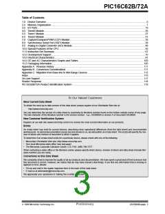
PIC16C62B/72A
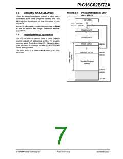
FIGURE 2-1: PROGRAM MEMORY MAP
AND STACK
2.0
MEMORY ORGANIZATION
There are two memory blocks in each of these micro-
controllers. Each block (Program Memory and Data
Memory) has its own bus, so that concurrent access
can occur.
PC<12:0>
CALL, RETURN
RETFIE, RETLW
13
Additional information on device memory may be found
in the PICmicro
(DS33023).
Mid-Range Reference Manual,
Stack Level 1
Stack Level 8
2.1
Program Memory Organization
The PIC16C62B/72A devices have a 13-bit program
counter capable of addressing an 8K x 14 program
memory space. Each device has 2K x 14 words of pro-
gram memory. Accessing a location above 07FFh will
cause a wraparound.
Reset Vector
0000h
The reset vector is at 0000h and the interrupt vector is
at 0004h.
Interrupt Vector
0004h
0005h
On-chip Program
Memory
07FFh
0800h
1FFFh
1999 Microchip Technology Inc.
Preliminary
DS35008B-page 7

 MICROCHIP [ MICROCHIP ]