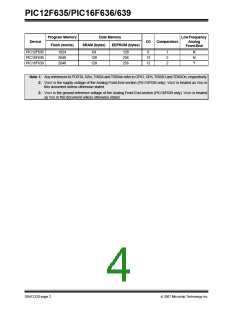
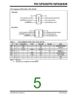
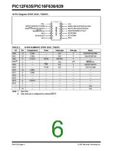
PIC12F635/PIC16F636/639
20-Pin Diagram
SSOP
1
2
3
4
5
6
7
8
9
10
20
19
18
VDD
RA5/T1CKI/OSC1/CLKIN
RA4/T1G/OSC2/CLKOUT
RA3/MCLR/VPP
VSS
RA0/C1IN+/ICSPDAT/ULPWU
RA1/C1IN-/VREF/ICSPCLK
RA2/TOCKI/INT/C1OUT
RC0/C2IN+
17
16
RC5
15
14
13
12
11
RC4/C2OUT
RC1/C2IN-/CS
RC3/LFDATA/RSSI/CCLK/SDIO
RC2/SCLK/ALERT
(3)
(4)
VDDT
VSST
LCZ
LCY
LCCOM
LCX
TABLE 4:
20-PIN SUMMARY
I/O
Pin
Analog Front-End Comparators
Timer
Interrupts
Pull-ups
Basic
RA0
19
18
17
—
—
—
C1IN+
C1IN-
—
—
IOC
IOC
Y
Y
Y
ICSPDAT/ULPWU
VREF/ICSPCLK
—
RA1
RA2
C1OUT
T0CKI
INT/IOC
RA3(1)
4
3
—
—
—
—
T1G
T1CKI
—
IOC
IOC
IOC
—
Y(2)
Y
MCLR/VPP
RA4
RA5
RC0
RC1
RC2
RC3
RC4
RC5
—
—
OSC2/CLKOUT
2
—
—
Y
OSC1/CLKIN
16
15
14
7
—
C2IN+
C2IN-
—
—
—
—
—
—
—
—
—
—
—
—
—
—
—
—
CS
—
—
—
ALERT
—
—
SCLK
CCLK/SDIO
—
LFDATA/RSSI
—
—
—
6
—
—
C2OUT
—
—
—
5
—
—
—
(3)
8
—
—
—
—
VDDT
(4)
—
13
11
10
9
—
—
—
—
VSST
—
LCX
LCY
LCZ
LCCOM
—
—
—
—
—
—
—
—
—
—
—
—
—
—
—
—
12
1
—
—
—
—
—
—
—
—
VDD
VSS
—
20
—
—
—
—
Note 1: Input only.
2: Only when pin is configured for external MCLR.
3: VDDT is the supply voltage of the Analog Front-End section (PIC16F639 only). VDDT is treated as VDD in
this document unless otherwise stated.
4: VSST is the ground reference voltage of the Analog Front-End section (PIC16F639 only). VSST is treated
as VSS in this document unless otherwise stated.
DS41232D-page 6
© 2007 Microchip Technology Inc.

 MICROCHIP [ MICROCHIP ]