MCP414X/416X/424X/426X
5.1
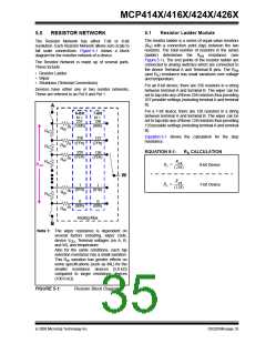
Resistor Ladder Module
5.0
RESISTOR NETWORK
The resistor ladder is a series of equal value resistors
(RS) with a connection point (tap) between the two
resistors. The total number of resistors in the series
(ladder) determines the RAB resistance (see
Figure 5-1). The end points of the resistor ladder are
connected to analog switches which are connected to
the device Terminal A and Terminal B pins. The RAB
(and RS) resistance has small variations over voltage
and temperature.
The Resistor Network has either 7-bit or 8-bit
resolution. Each Resistor Network allows zero scale to
full scale connections. Figure 5-1 shows a block
diagram for the resistive network of a device.
The Resistor Network is made up of several parts.
These include:
• Resistor Ladder
• Wiper
• Shutdown (Terminal Connections)
For an 8-bit device, there are 256 resistors in a string
between terminal A and terminal B. The wiper can be
set to tap onto any of these 256 resistors thus providing
257 possible settings (including terminal A and terminal
B).
Devices have either one or two resistor networks,
These are referred to as Pot 0 and Pot 1.
A
For a 7-bit device, there are 128 resistors in a string
between terminal A and terminal B. The wiper can be
set to tap onto any of these 128 resistors thus providing
129 possible settings (including terminal A and terminal
B).
8-Bit
N =
257
7-Bit
N =
128
(100h)
(80h)
(1)
RW
RS
RS
RS
Equation 5-1 shows the calculation for the step
resistance.
256
(FFh)
127
(7Fh)
(1)
(1)
RW
RW
EQUATION 5-1:
R CALCULATION
255
(FEh)
126
(7Eh)
S
RAB
RAB
RS = -------------
8-bit Device
(256)
W
RAB
RS = -------------
(128)
7-bit Device
1
1
(01h)
(01h)
(1)
(1)
RW
RW
RS
0
0
(00h)
(00h)
Analog Mux
B
Note 1: The wiper resistance is dependent on
several factors including, wiper code,
device VDD, Terminal voltages (on A, B,
and W), and temperature.
Also for the same conditions, each tap
selection resistance has a small variation.
This RW variation has greater effects on
some specifications (such as INL) for the
smaller resistance devices (5.0 kΩ)
compared to larger resistance devices
(100.0 kΩ).
FIGURE 5-1:
Resistor Block Diagram.
© 2008 Microchip Technology Inc.
DS22059B-page 35

 MICROCHIP [ MICROCHIP ]