MCP2515
REGISTER 4-3:
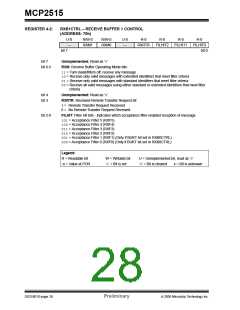
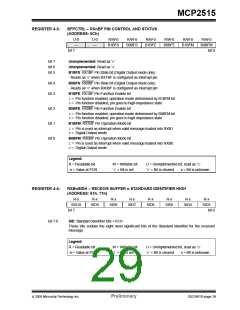
BFPCTRL – RXnBF PIN CONTROL AND STATUS
(ADDRESS: 0Ch)
U-0
—
U-0
—
R/W-0
R/W-0
R/W-0
R/W-0
R/W-0
R/W-0
B1BFS
B0BFS
B1BFE
B0BFE
B1BFM
B0BFM
bit 7
bit 0
bit 7
bit 6
bit 5
Unimplemented: Read as ‘0’
Unimplemented: Read as ‘0’
B1BFS: RX1BF Pin State bit (Digital Output mode only)
- Reads as ‘0’ when RX1BF is configured as interrupt pin
B0BFS: RX0BF Pin State bit (Digital Output mode only)
- Reads as ‘0’ when RX0BF is configured as interrupt pin
B1BFE: RX1BF Pin Function Enable bit
bit 4
bit 3
1= Pin function enabled, operation mode determined by B1BFM bit
0= Pin function disabled, pin goes to high-impedance state
bit 2
bit 1
bit 0
B0BFE: RX0BF Pin Function Enable bit
1= Pin function enabled, operation mode determined by B0BFM bit
0= Pin function disabled, pin goes to high-impedance state
B1BFM: RX1BF Pin Operation Mode bit
1= Pin is used as interrupt when valid message loaded into RXB1
0= Digital Output mode
B0BFM: RX0BF Pin Operation Mode bit
1= Pin is used as interrupt when valid message loaded into RXB0
0= Digital Output mode
Legend:
R = Readable bit
-n = Value at POR
W = Writable bit
U = Unimplemented bit, read as ‘0’
‘0’ = Bit is cleared x = Bit is unknown
‘1’ = Bit is set
REGISTER 4-4:
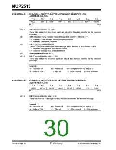
RXBnSIDH – RECEIVE BUFFER n STANDARD IDENTIFIER HIGH
(ADDRESS: 61h, 71h)
R-x
R-x
R-x
R-x
R-x
R-x
R-x
R-x
SID10
SID9
SID8
SID7
SID6
SID5
SID4
SID3
bit 7
bit 0
bit 7-0
SID: Standard Identifier bits <10:3>
These bits contain the eight most significant bits of the Standard Identifier for the received
message
Legend:
R = Readable bit
-n = Value at POR
W = Writable bit
U = Unimplemented bit, read as ‘0’
‘0’ = Bit is cleared x = Bit is unknown
‘1’ = Bit is set
© 2005 Microchip Technology Inc.
Preliminary
DS21801D-page 29

 MICROCHIP [ MICROCHIP ]