MCP2021/2
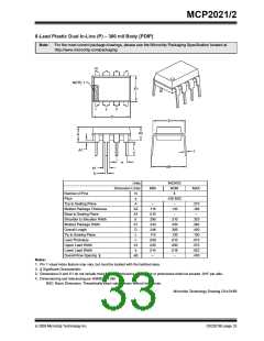
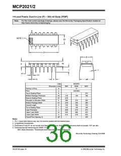
14-Lead Plastic Dual In-Line (P) – 300 mil Body [PDIP]
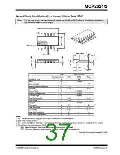
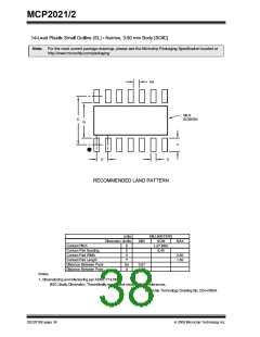
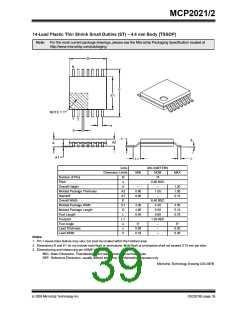
Note: For the most current package drawings, please see the Microchip Packaging Specification located at
http://www.microchip.com/packaging
N
NOTE 1
E1
3
1
2
D
E
A2
A
L
c
A1
b1
b
e
eB
Units
Dimension Limits
INCHES
NOM
14
.100 BSC
–
MIN
MAX
Number of Pins
Pitch
N
e
A
Top to Seating Plane
–
.210
.195
–
Molded Package Thickness
Base to Seating Plane
Shoulder to Shoulder Width
Molded Package Width
Overall Length
Tip to Seating Plane
Lead Thickness
Upper Lead Width
A2
A1
E
E1
D
L
c
b1
b
eB
.115
.015
.290
.240
.735
.115
.008
.045
.014
–
.130
–
.310
.250
.750
.130
.010
.060
.018
–
.325
.280
.775
.150
.015
.070
.022
.430
Lower Lead Width
Overall Row Spacing §
Notes:
1. Pin 1 visual index feature may vary, but must be located with the hatched area.
2. § Significant Characteristic.
3. Dimensions D and E1 do not include mold flash or protrusions. Mold flash or protrusions shall not exceed .010" per side.
4. Dimensioning and tolerancing per ASME Y14.5M.
BSC: Basic Dimension. Theoretically exact value shown without tolerances.
Microchip Technology Drawing C04-005B
DS22018E-page 36
© 2009 Microchip Technology Inc.

 MICROCHIP [ MICROCHIP ]