MCP2021/2
2.3
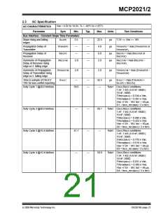
AC Specification (Continued)
VBB = 6.0V to 18.0V; TA = -40°C to +125°C
AC CHARACTERISTICS
Parameter
Sym
Min.
Typ.
Max.
Units
Test Conditions
Voltage Regulator
Bus Activity Debounce time
tBDB
5
10
20
µs
µs
Bus debounce time
Bus Activity to Voltage
Regulator Enabled
tBACTVE
100
250
500
After Bus debounce time
Voltage Regulator Enabled
to Ready
tVEVR
tCSOR
(Note 1)
—
—
—
—
1200
500
µs
µs
Chip Select to Operation
Ready
(Note 1)
Chip Select to Power-down
Short circuit to shut-down
RESET Timing
tCSPD
—
—
—
80
µs
µs
tSHUTDOWN
20
100
VREG OK detect to RESET
inactive
tRPU
tRPD
—
—
—
—
10.0
10.0
µs
µs
VREG OK detect to RESET
active
Note 1: Time depends on external capacitance and load.
2.4
Thermal Specifications
THERMAL CHARACTERISTICS
Parameter
Symbol
Typ
Max
Units
Test Conditions
—
—
Recovery Temperature
θRECOVERY
θSHUTDOWN
tTHERM
+140
+150
1.5
°C
°C
ms
Shutdown Temperature
Short Circuit Recovery Time
Thermal Package Resistances
Thermal Resistance, 8L-DFN
Thermal Resistance, 8L-PDIP
Thermal Resistance, 8L-SOIC
Thermal Resistance, 14L-PDIP
Thermal Resistance, 14L-SOIC
Thermal Resistance, 14L-TSSOP
5.0
θJA
θJA
θJA
θJA
θJA
θJA
35.7
89.3
149.5
70
—
—
—
—
—
—
°C/W
°C/W
°C/W
°C/W
°C/W
°C/W
95.3
100
Note 1: The maximum power dissipation is a function of TJMAX, ΘJA and ambient temperature TA. The maximum
allowable power dissipation at an ambient temperature is PD = (TJMAX - TA) ΘJA. If this dissipation is
exceeded, the die temperature will rise above 150°C and the MCP2021 will go into thermal shutdown.
DS22018E-page 22
© 2009 Microchip Technology Inc.

 MICROCHIP [ MICROCHIP ]