MIC4423/4424/4425
Micrel
requires attention to the ground path. Two things other than
the driver affect the rate at which it is possible to turn a load
off: The adequacy of the grounding available for the driver,
andtheinductanceoftheleadsfromthedrivertotheload.The
latter will be discussed in a separate section.
Application Information
Although the MIC4423/24/25 drivers have been specifically
constructed to operate reliably under any practical
circumstances, there are nonetheless details of usage which
will provide better operation of the device.
Best practice for a ground path is obviously a well laid out
ground plane. However, this is not always practical, and a
poorly-laidoutgroundplanecanbeworsethannone.Attention
to the paths taken by return currents even in a ground plane
isessential. Ingeneral, theleadsfromthedrivertoitsload, the
drivertothepowersupply,andthedrivertowhateverisdriving
it should all be as low in resistance and inductance as
possible. Of the three paths, the ground lead from the driver
to the logic driving it is most sensitive to resistance or
inductance, andgroundcurrentfromtheloadarewhatismost
likelytocausedisruption. Thus, thesegroundpathsshouldbe
arranged so that they never share a land, or do so for as short
a distance as is practical.
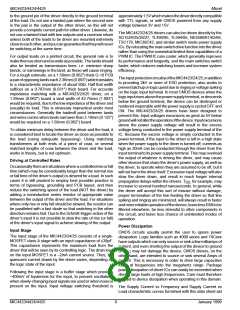
Supply Bypassing
Charging and discharging large capacitive loads quickly
requires large currents. For example, charging 2000pF from
0 to 15 volts in 20ns requires a constant current of 1.5A. In
practice, the charging current is not constant, and will usually
peak at around 3A. In order to charge the capacitor, the driver
must be capable of drawing this much current, this quickly,
from the system power supply. In turn, this means that as far
as the driver is concerned, the system power supply, as seen
by the driver, must have a VERY low impedance.
As a practical matter, this means that the power supply bus
must be capacitively bypassed at the driver with at least 100X
the load capacitance in order to achieve optimum driving
speed. It also implies that the bypassing capacitor must have
very low internal inductance and resistance at all frequencies
of interest. Generally, this means using two capacitors, one a
high-performance low ESR film, the other a low internal
resistance ceramic, as together the valleys in their two
impedance curves allow adequate performance over a broad
enough band to get the job done. PLEASE NOTE that many
film capacitors can be sufficiently inductive as to be useless
for this service. Likewise, many multilayer ceramic capacitors
have unacceptably high internal resistance. Use capacitors
intended for high pulse current service (in-house we use
WIMA™ film capacitors and AVX Ramguard™ ceramics;
severalothermanufacturersofequivalentdevicesalsoexist).
The high pulse current demands of capacitive drivers also
mean that the bypass capacitors must be mounted very close
to the driver in order to prevent the effects of lead inductance
or PCB land inductance from nullifying what you are trying to
accomplish. For optimum results the sum of the lengths of the
leads and the lands from the capacitor body to the driver body
should total 2.5cm or less.
To illustrate what can happen, consider the following: The
inductance of a 2cm long land, 1.59mm (0.062") wide on a
PCB with no ground plane is approximately 45nH. Assuming
a dl/dt of 0.3A/ns (which will allow a current of 3A to flow after
10ns, and is thus slightly slow for our purposes) a voltage of
13.5 Volts will develop along this land in response to our
postulated∆Ι. Fora1cmland, (approximately15nH)4.5Volts
isdeveloped.Eitherway,anyoneusingTTL-levelinputsignals
to the driver will find that the response of their driver has been
seriously degraded by a common ground path for input to and
output from the driver of the given dimensions. Note that this
is before accounting for any resistive drops in the circuit. The
resistive drop in a 1.59mm (0.062") land of 2oz. Copper
carrying 3A will be about 4mV/cm (10mV/in) at DC, and the
resistance will increase with frequency as skin effect comes
into play.
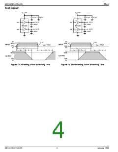
The problem is most obvious in inverting drivers where the
input and output currents are in phase so that any attempt to
raisethedriver’sinputvoltage(inordertoturnthedriver’sload
off) is countered by the voltage developed on the common
groundpathasthedriverattemptstodowhatitwassupposed
to. It takes very little common ground path, under these
circumstances, to alter circuit operation drastically.
Bypass capacitance, and its close mounting to the driver
serves two purposes. Not only does it allow optimum
performance from the driver, it minimizes the amount of lead
lengthradiatingathighfrequencyduringswitching,(duetothe
large ∆ I) thus minimizing the amount of EMI later available for
system disruption and subsequent cleanup. It should also be
noted that the actual frequency of the EMI produced by a
driver is not the clock frequency at which it is driven, but is
related to the highest rate of change of current produced
during switching, a frequency generally one or two orders of
magnitude higher, and thus more difficult to filter if you let it
permeateyoursystem.Goodbypassingpracticeisessential
to proper operation of high speed driver ICs.
Output Lead Inductance
The same descriptions just given for PCB land inductance
apply equally well for the output leads from a driver to its load,
except that commonly the load is located much further away
from the driver than the driver’s ground bus.
Generally, the best way to treat the output lead inductance
problem, when distances greater than 4cm (2") are involved,
requires treating the output leads as a transmission line.
Unfortunately, as both the output impedance of the driver and
theinputimpedanceoftheMOSFETgateareatleastanorder
of magnitude lower than the impedance of common coax,
using coax is seldom a cost-effective solution. A twisted pair
works about as well, is generally lower in cost, and allows use
of a wider variety of connectors. The second wire of the
twisted pair should carry common from as close as possible
Grounding
Both proper bypassing and proper grounding are necessary
for optimum driver operation. Bypassing capacitance only
allows a driver to turn the load ON. Eventually (except in rare
circumstances) it is also necessary to turn the load OFF. This
January 1999
7
MIC4423/4424/4425

 MICREL [ MICREL SEMICONDUCTOR ]