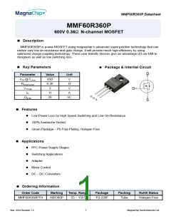
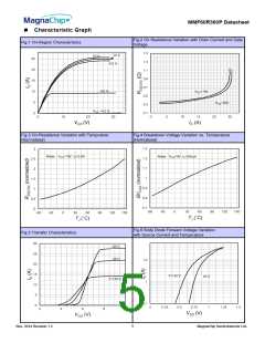
MMF60R360P Datasheet
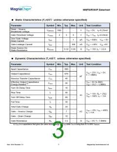
Static Characteristics (Tc=25℃ unless otherwise specified)
Parameter
Symbol Min. Typ. Max. Unit Test Condition
Drain – Source
Breakdown voltage
V(BR)DSS
VGS(th)
IDSS
600
-
3
-
-
4
V
V
VGS = 0V, ID=0.25mA
VDS = VGS, ID=0.25mA
VDS = 600V, VGS = 0V
VGS = ±30V, VDS =0V
VGS = 10V, ID = 3.8 A
Gate Threshold Voltage
2
-
Zero Gate Voltage
Drain Current
1
μA
nA
Ω
Gate Leakage Current
IGSS
-
-
100
Drain-Source On
State Resistance
RDS(ON)
-
0.32 0.36
Dynamic Characteristics (Tc=25℃ unless otherwise specified)
Parameter
Symbol Min. Typ. Max. Unit Test Condition
Input Capacitance
Output Capacitance
Reverse Transfer Capacitance
Ciss
Coss
Crss
Co(er)
td(on)
tr
-
-
-
-
-
-
-
-
-
-
-
-
890
670
40
26
18
40
80
30
28
7
-
-
-
-
-
-
-
-
-
-
-
-
VDS = 25V, VGS = 0V,
f = 1.0MHz
pF
ns
Effective Output Capacitance
Energy Related (4)
VDS = 0V to 480V,
VGS = 0V,f = 1.0MHz
Turn On Delay Time
Rise Time
VGS = 10V, RG = 25Ω,
VDS = 300V, ID = 11A
Turn Off Delay Time
Fall Time
td(off)
tf
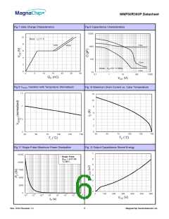
Total Gate Charge
Gate – Source Charge
Gate – Drain Charge
Gate Resistance
Qg
VGS = 10V, VDS = 480V,
ID = 11A
Qgs
Qgd
RG
nC
10
3.5
Ω
VGS = 0V, f = 1.0MHz
4) Co(er) is a capacitance that gives the same stored energy as COSS while VDS is rising from 0V to 80% V(BR)DSS
3
Nov. 2014 Revision 1.2
MagnaChip Semiconductor Ltd.

 MGCHIP [ MagnaChip ]