starts from 0%, up to 100%, with a step of 1/256.
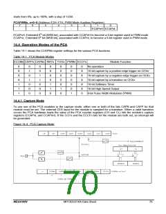
PCAPWMn, n=0~5 (Address=F2H~F7H, PWM Mode Auxiliary Registers)
7
6
5
4
3
2
1
0
-
-
-
-
-
-
ECAPnH ECAPnL
ECAPnH: Extended 9th bit (MSB bit), associated with CCAPnH to become a 9-bit register used in PWM mode.
ECAPnL: Extended 9th bit (MSB bit), associated with CCAPnL to become a 9-bit register used in PWM mode.
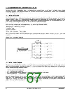
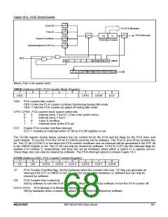
14.4 Operation Modes of the PCA
Table 14-1 shows the CCAPMn register settings for the various PCA functions.
Table 14-1. PCA Module Modes
ECOMn CAPPn CAPNn MATn TOGn PWMn ECCFn
Module Function
0
X
X
X
1
1
1
0
1
0
1
0
0
0
0
0
1
1
0
0
0
0
0
0
0
1
1
0
0
0
0
0
0
1
0
0
0
0
0
0
0
1
0
X
X
X
X
X
0
No operation
16-bit capture by a positive-edge trigger on CEXn
16-bit capture by a negative-edge trigger on CEXn
16-bit capture by a transition on CEXn
16-bit Software Timer
16-bit High Speed Output
8-bit Pulse Width Modulator (PWM)
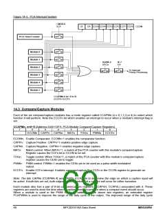
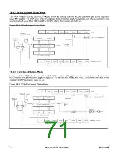
14.4.1 Capture Mode
To use one of the PCA modules in the capture mode, either one or both of the bits CAPN and CAPP for that
module must be set. The external CEX input for the module is sampled for a transition. When a valid transition
occurs the PCA hardware loads the value of the PCA counter registers (CH and CL) into the module’s capture
registers (CCAPnL and CCAPnH). If the CCFn and the ECCFn bits for the module are both set, an interrupt will
be generated.
Figure 14-4. PCA Capture Mode
MEGAWIN
MPC82G516A Data Sheet
70

 MEGAWIN [ MEGAWIN TECHNOLOGY CO., LTD ]