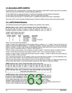
14 Programmable Counter Array (PCA)
The MPC82G516A is equipped with a Programmable Counter Array (PCA), which provides more timing
capabilities with less CPU intervention than the standard timer/counters. Its advantages include reduced software
overhead and improved accuracy.
14.1 PCA Overview
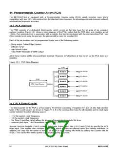
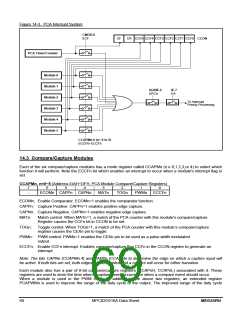
The PCA consists of a dedicated timer/counter which serves as the time base for an array of six compare/
capture modules. Figure 14-1 shows a block diagram of the PCA. Notice that the PCA timer and modules are all
16-bits. If an external event is associated with a module, that function is shared with the corresponding Port 1 pin.
If the module is not using the port pin, the pin can still be used for standard I/O.
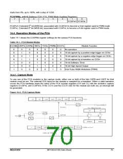
Each of the six modules can be programmed in any one of the following modes:
- Rising and/or Falling Edge Capture
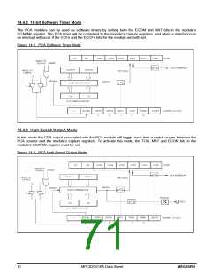
- Software Timer
- High Speed Output
- Pulse Width Modulator (PWM) Output
All of these modes will be discussed later in detail. However, let's first look at how to set up the PCA timer and
modules.
Figure 14-1. PCA Block Diagram
16 Bit
P1.2/CEX0
P1.3/CEX1
P1.4/CEX2
P1.5/CEX3
P1.6/CEX4
P1.7/CEX5
Module 0
Module 1
Module 2
Module 3
Module 4
Module 5
16 Bit
PCA Timer/Counter
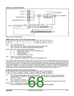
14.2 PCA Timer/Counter
The timer/counter for the PCA is a free-running 16-bit timer consisting of registers CH and CL (the high and low
bytes of the count values), as shown in Figure 14-2. It is the common time base for all modules and its clock input
can be selected from the following source:
- 1/12 the system clock frequency,
- 1/2 the system clock frequency,
- the Timer 0 overflow, which allows for a range of slower clock inputs to the timer.
- external clock input, 1-to-0 transitions, on ECI pin (P1.1).
Special Function Register CMOD contains the Count Pulse Select bits (CPS1 and CPS0) to specify the PCA
timer input. This register also contains the ECF bit which enables an interrupt when the counter overflows. In
addition, the user has the option of turning off the PCA timer during Idle Mode by setting the Counter Idle bit
(CIDL). This can further reduce power consumption during Idle mode.
67
MPC82G516A Data Sheet
MEGAWIN

 MEGAWIN [ MEGAWIN TECHNOLOGY CO., LTD ]