24 Reset Sources
Reset can be triggered from the following reset sources (see Figure 24-1):
• Power-on reset
• Hardware reset from RST-pin
• Watchdog Timer reset
• Software reset
• Brownout reset from Power Monitor
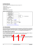
Figure 24-1. Block Diagram of Reset
Power-on Reset
(During Power Up)
Hardware Reset
(A High on RST-pin)
Watchdog Timer
Reset
Internal Reset
Software Reset
(Write '1' to ISPCR.5)
Brownout Detection
ENLVRO
ENLVRC
VDD Power
VOPF (3.7V)
-
+
Comp.
LDO
Brownout
Reset
Output Power
-
+
Comp.
VCPF (2.4V)
Note: ENLVRO and ENLVRC are the Hardware Options.
24.1 Power-On Reset
Power-on reset (POR) is used to internally reset the MCU during power-up. The MCU will keep in reset state and
will not start to work until the VDD power rises above VPOR (the POR threshold voltage). And, the reset state is
activated again whenever the VDD power falls below VPOR. During a power cycle, VDD must fall below VPOR
before power is reapplied in order to ensure a power-on reset. See Section 30: DC Characteristics for VPOR
.
24.2 Hardware Reset from RST-Pin
A reset is accomplished by holding the RST pin HIGH for at least 24 oscillator periods while the oscillator is
running. To ensure a reliable power-up reset, the hardware reset from RST pin is necessary.
24.3 Watchdog Timer Reset
When the Watchdog Timer is enabled, it will increment every 12 system clock cycles (12/Fosc) while the
oscillator is running. And, the user needs to service it to avoid an overflow, which will generate an internal reset
signal.
117
MPC82G516A Data Sheet
MEGAWIN

 MEGAWIN [ MEGAWIN TECHNOLOGY CO., LTD ]