MX27L1000
NOTICE:
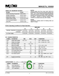
ABSOLUTE MAXIMUM RATINGS
Stresses greater than those listed under ABSOLUTE
MAXIMUM RATINGS may cause permanent damage to the
device. This is a stress rating only and functional operation
of the device at these or any other conditions above those
indicated in the operational sections of this specification is
not implied. Exposure to absolute maximum rating
conditions for extended period may affect reliability.
RATING
VALUE
AmbientOperatingTemperature -40oCto85oC
StorageTemperature
Applied Input Voltage
AppliedOutputVoltage
VCC to Ground Potential
V9 & VPP
-65oCto125oC
-0.5V to 7.0V
-0.5V to VCC+0.5V
-0.5V to 7.0V
NOTICE:
Specifications contained within the following tables are
subject to change.
-0.5V to 13.5V
DC/AC Operating Conditions for Read Operation
MX27L1000
-90
-12
0°C to 70°C
-15
-20
-25
Operating Temperature Commercial 0°C to 70°C
Industrial
0°C to 70°C
0°C to 70°C 0°C to 70°C
-40°C to 85°C -40°C to 85°C -40°C to 85°C -40°C to 85°C -40°C to 85°C
Vcc Power Supply
2.7V to 3.6V
2.7V to 3.6V 2.7V to 3.6V
2.7V to 3.6V 2.7V to 3.6V
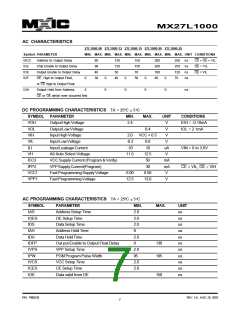
DC CHARACTERISTICS
SYMBOL PARAMETER
MIN.
MAX.
UNIT
V
CONDITIONS
VOH
VOL
VIH
OutputHighVoltage
VCC - 0.3
IOH = -100uA VCC=3.0V
IOL = 2.1mA, VCC = 3.0V
OutputLowVoltage
Input High Voltage
0.3
Vcc + 0.5
0.6
V
2.0
-0.3
-10
V
VIL
Input Low Voltage
V
2.7V < VCC < 3.6V
VIN = 0 to 3.6V
ILI
InputLeakageCurrent
OutputLeakageCurrent
VCCPower-DownCurrent
VCCStandbyCurrent
VCC Active Current
10
uA
uA
uA
mA
mA
ILO
-10
10
VOUT = 0 to 3.6V
CE = VCC ±0.3V
CE = VIH
ICC3
ICC2
ICC1
10
0.25
20
CE = VIH, f=5MHz, lout = OmA,
Vcc=3.6V
IPP
SupplyCurrentRead
10
uA
CE = OE = VIL, VPP = VCC
CAPACITANCE TA = 25oC, f = 1.0 MHz (Sampled only)
SYMBOL PARAMETER
TYP.
8
MAX.
12
UNIT
CONDITIONS
VIN = 0V
CIN
InputCapacitance
OutputCapacitance
VPP Capacitance
pF
pF
pF
COUT
CVPP
8
12
VOUT = 0V
VPP = 0V
18
25
P/N: PM0238
REV. 3.8 , AUG. 26, 2003
6

 Macronix [ MACRONIX INTERNATIONAL ]