Hig h -S p e e d , Mic ro p o w e r, Lo w -Vo lt a g e ,
S OT2 3 , Ra il-t o -Ra il I/O Co m p a ra t o rs
Ze ro -Cro s s in g De t e c t o r
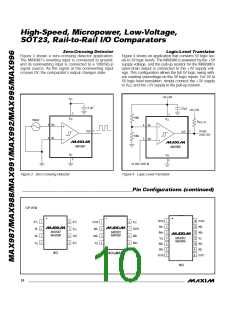
Figure 3 shows a zero-crossing detector application.
The MAX987’s inverting input is connected to ground,
and its noninverting input is connected to a 100mVp-p
signal source. As the signal at the noninverting input
crosses 0V, the comparator’s output changes state.
Lo g ic -Le ve l Tra n s la t o r
Figure 4 shows an application that converts 5V logic lev-
els to 3V logic levels. The MAX988 is powered by the +5V
supply voltage, and the pull-up resistor for the MAX988’s
open-drain output is connected to the +3V supply volt-
age. This configuration allows the full 5V logic swing with-
out creating overvoltage on the 3V logic inputs. For 3V to
5V logic-level translation, simply connect the +3V supply
to V and the +5V supply to the pull-up resistor.
CC
+5V (+3V)
V
CC
0.1µF
0.1µF
+3V (+5V)
2
2
100k
V
CC
V
CC
100mV
R
PULL-UP
4
3
IN+
IN-
4
3
IN-
1
OUT
3V (5V)
LOGIC OUT
1
OUT
100k
IN+
MAX987
MAX988
V
EE
V
EE
5
5
5V (3V) LOGIC IN
Figure 3. Zero-Crossing Detector
Figure 4. Logic-Level Translator
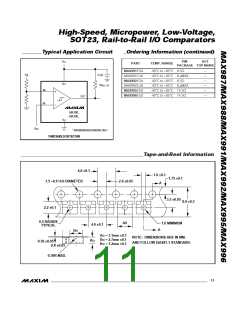
_____________________________________________P in Co n fig u ra t io n s (c o n t in u e d )
TOP VIEW
OUTA
INA-
1
2
3
4
5
6
7
14 OUTD
13 IND-
12 IND+
N.C.
IN-
1
2
3
4
8
7
6
5
N.C.
OUTA
INA-
1
2
3
4
8
7
6
5
V
CC
V
CC
OUTB
INB-
MAX987
MAX988
MAX991
MAX992
INA+
OUT
N.C.
IN+
INA+
V
CC
11
V
EE
MAX995
MAX996
V
EE
V
EE
INB+
INB+
INB-
10 INC+
9
8
INC-
SO
SO/µMAX
OUTB
OUTC
78125/MAX96
SO
10 ______________________________________________________________________________________

 MAXIM [ MAXIM INTEGRATED PRODUCTS ]