2.6W Stereo Audio Power Amplifiers and
DirectDrive Headphone Amplifiers
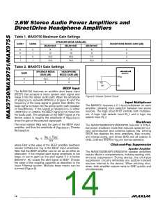
Table 1. MAX9750 Maximum Gain Settings
SPꢀAKꢀR MODꢀ GAIN (dB)
GAIN1
GAIN2
HꢀADPHONꢀ MODꢀ GAIN (dB)
MAX9750A
MAX9750B
MAX9750C
0
0
1
1
0
1
0
1
9
15
18
6
9
0
0
3
3
12
10.5
13.5
16.5
19.5
7.5
10.5
Table 2. MAX9751 Gain Settings
SPꢀAKꢀR MODꢀ
GAIN (dB)
HꢀADPHONꢀ
MODꢀ GAIN (dB)
GAIN
MAX9750
HPV
VOL
DD
0
1
10.5
9
3
0
V
REF
DAC
BEEP Input
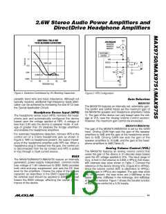
The MAX9750 features an audible alert beep input
(BEEP) that accepts a mono system alert signal and
mixes it into the stereo audio path. When the amplitude
Figure 6. Volume Control Circuit
of V
exceeds 800mV
(Figure 8) and the
P-P
BEEP(OUT)
Input Multiplexer
frequency of the beep signal is greater than 300Hz, the
beep signal is mixed into the active audio path (speaker
The MAX9751 features a 2:1 input multiplexer on each
amplifier, allowing input selection between two stereo
sources. The logic input IN1/2 controls both multiplex-
ers. A logic high selects input IN_1 and a logic low
selects input IN_2.
or headphone). If the signal at V
is either
BEEP(OUT)
<800mV
or <300Hz, the BEEP signal is not mixed into
the audio path. The amplitude of the BEEP signal at the
P-P
device output is roughly the amplitude of V
times the gain of the selected signal path.
BEEP(OUT)
Shutdown
The MAX9750/MAX9751/MAX9755 features a 0.2µA,
low-power shutdown mode that reduces quiescent cur-
rent consumption and extends battery life. Driving
SHDN low disables the drive amplifiers, bias circuitry,
and charge pump, and drives BIAS and all outputs to
The input resistor (R ) sets the gain of the BEEP input
B
amplifier, and thus the amplitude of V
. Choose
BEEP(OUT)
R based on:
B
V
× R
0.8
IN
INT
R
≤
B
GND. Connect SHDN to V
for normal operation.
DD
Click-and-Pop Suppression
where R
is the value of the BEEP amplifier feedback
INT
resistor (47kΩ) and V is the BEEP input amplitude.
IN
Speaker Amplifier
The MAX9750/MAX9751/MAX9755 speaker amplifiers
feature Maxim’s comprehensive, industry-leading click-
and-pop suppression. During startup, the click-pop
suppression circuitry eliminates any audible transient
sources internal to the device. When entering shut-
down, both amplifier outputs ramp to GND quickly and
simultaneously.
Note that the BEEP amplifier can be set up as either an
attenuator, if the original alert signal amplitude is too
large, or set to gain up the alert signal if it is below
800mV . AC couple the alert signal to BEEP. Choose
P-P
the value of the coupling capacitor as described in the
Input Filtering section. Multiple beep inputs can be
summed (Figure 8).
14 ______________________________________________________________________________________

 MAXIM [ MAXIM INTEGRATED PRODUCTS ]