2.6W Stereo Audio Power Amplifiers and
DirectDrive Headphone Amplifiers
significant amount of DC current flows to the headphone,
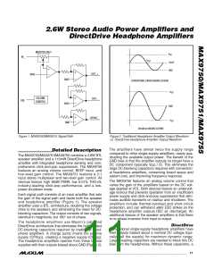
LOW-FREQUENCY ROLLOFF
resulting in unnecessary power dissipation and possible
(R = 16Ω)
L
damage to both headphone and headphone amplifier.
0
Maxim’s patented DirectDrive architecture uses a charge
pump to create an internal negative supply voltage. This
allows the MAX9750/MAX9751/MAX9755 headphone
amplifier output to be biased about GND, almost dou-
bling the dynamic range while operating from a single
supply. With no DC component, there is no need for the
large DC-blocking capacitors. Instead of two large
capacitors (220µF typ), the MAX9750/MAX9751/
MAX9755 charge pump requires only two small ceramic
capacitors (1µF typ), conserving board space, reducing
cost, and improving the frequency response of the head-
phone amplifier. See the Output Power vs. Charge-Pump
Capacitance and Load Resistance graph in the Typical
Operating Characteristics for details of the possible
capacitor values.
-3
DirectDrive
330µF
220µF
100µF
-6
-9
-12
-15
-18
33µF
-21
-24
-27
-30
10
100
1k
FREQUENCY (Hz)
10k
100k
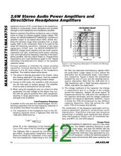
Figure 3. Low-Frequency Attenuation of Common DC-Blocking
Capacitor Values
Previous attempts to eliminate the output coupling
capacitors involved biasing the headphone return
(sleeve) to the DC bias voltage of the headphone
amplifiers. This method raised some issues:
the filter can attenuate low-frequency signals within
the audio band. Larger values of C
reduce the
OUT
attenuation but are physically larger, more expen-
sive capacitors. Figure 3 shows the relationship
1) The sleeve is typically grounded to the chassis. Using
this biasing approach, the sleeve must be isolated
from system ground, complicating product design.
between the size of C
and the resulting low-fre-
OUT
quency attenuation. Note that the -3dB point for a
16Ω headphone with a 100µF blocking capacitor is
100Hz, well within the audio band.
2) During an ESD strike, the amplifier’s ESD structures
are the only path to system ground. The amplifier
must be able to withstand the full ESD strike.
2) The voltage coefficient of the capacitor, the change
in capacitance due to a change in the voltage
across the capacitor, distorts the audio signal. At
frequencies around the -3dB point, the reactance of
the capacitor dominates, and the voltage coefficient
appears as frequency-dependent distortion. Figure
4 shows the THD+N introduced by two different
capacitor dielectrics. Note that around the -3dB
point, THD+N increases dramatically.
3) When using the headphone jack as a lineout to other
equipment, the bias voltage on the sleeve may con-
flict with the ground potential from other equipment,
resulting in large ground-loop current and possible
damage to the amplifiers.
Low-Frequency Response
In addition to the cost and size disadvantages, the DC-
blocking capacitors limit the low-frequency response of
the amplifier and distort the audio signal:
The combination of low-frequency attenuation and fre-
quency-dependent distortion compromises audio
reproduction. DirectDrive improves low-frequency
reproduction in portable audio equipment that empha-
sizes low-frequency effects such as multimedia lap-
tops, and MP3, CD, and DVD players.
1) The impedance of the headphone load to the DC-
blocking capacitor forms a highpass filter with the
-3dB point determined by:
1
f
=
−3dB
2πR C
L
OUT
Charge Pump
The MAX9750/MAX9751/MAX9755 feature a low-noise
charge pump. The 550kHz switching frequency is well
beyond the audio range, and does not interfere with the
audio signals. The switch drivers feature a controlled
switching speed that minimizes noise generated by turn-
on and turn-off transients. Limiting the switching speed of
the charge pump minimizes the di/dt noise caused by the
where R is the impedance of the headphone and
L
C
OUT
is the value of the DC-blocking capacitor.
The highpass filter is required by conventional sin-
gle-ended, single-supply headphone amplifiers to
block the midrail DC component of the audio signal
from the headphones. Depending on the -3dB point,
12 ______________________________________________________________________________________

 MAXIM [ MAXIM INTEGRATED PRODUCTS ]