2.6W Stereo Audio Power Amplifiers and
DirectDrive Headphone Amplifiers
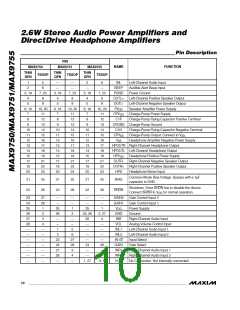
Pin Description
PIN
NAMꢀ
FUNCTION
MAX9750
MAX9751
MAX9755
THIN
QFN
THIN
QFN
THIN
QFN
TSSOP
TSSOP
TSSOP
1
5
6
—
—
—
2
6
—
INL
Left-Channel Audio Input
2
—
—
BEEP
Audible Alert Beep Input
3, 19
4
7, 23
8
3, 19
4
7, 23
8
3, 19
4
7, 23
8
PGND
OUTL+
OUTL-
Power Ground
Left-Channel Positive Speaker Output
Left-Channel Negative Speaker Output
Speaker Amplifier Power Supply
Charge-Pump Power Supply
5
9
5
9
5
9
6, 16
7
10, 20
11
12
13
14
15
16
17
18
19
21
22
24
6, 16
7
10, 20
11
6, 16
7
10, 20
11
PV
DD
CPV
DD
8
8
12
8
12
C1P
Charge-Pump Flying-Capacitor Positive Terminal
9
9
13
9
13
CPGND Charge-Pump Ground
C1N Charge-Pump Flying-Capacitor Negative Terminal
CPV Charge-Pump Output. Connect to V
10
11
12
13
14
15
17
18
20
10
11
12
13
14
15
17
18
20
14
10
11
12
13
14
15
17
18
20
14
15
15
.
SS
SS
16
16
V
Headphone Amplifier Negative Power Supply
SS
17
17
HPOUTR Right-Channel Headphone Output
HPOUTL Left-Channel Headphone Output
18
18
19
19
HPV
Headphone Positive Power Supply
Right-Channel Negative Speaker Output
Right-Channel Positive Speaker Output
Headphone Sense Input
DD
21
21
OUTR-
OUTR+
HPS
22
22
24
24
Common-Mode Bias Voltage. Bypass with a 1µF
capacitor to GND.
21
22
25
26
21
22
25
26
21
22
25
26
BIAS
Shutdown. Drive SHDN low to disable the device.
SHDN
Connect SHDN to V
for normal operation.
DD
23
24
25
26
27
28
—
—
—
—
—
—
—
27
28
1
—
—
25
26
—
—
1
—
—
1
—
—
—
—
GAIN2
GAIN1
Gain Control Input 2
Gain Control Input 1
Power Supply
25
1
V
DD
2
2
23, 26
28
2, 27
4
GND
INR
Ground
3
—
—
5
Right-Channel Audio Input
Analog Volume Control Input
Left-Channel Audio Input 1
Left-Channel Audio Input 2
Input Select
4
—
—
VOL
—
—
—
—
—
—
—
—
—
INL1
INL2
IN1/2
GAIN
INR1
INR2
N.C.
2
6
—
—
23
24
27
28
—
27
28
3
—
—
24
28
—
Gain Select
—
Right-Channel Audio Input 1
Right-Channel Audio Input 2
No Connection. Not internally connected.
4
—
—
—
1, 27
3, 5
10 ______________________________________________________________________________________

 MAXIM [ MAXIM INTEGRATED PRODUCTS ]