SMBus Level 2 Battery Charger
with Remote Sense
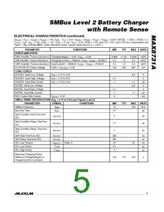
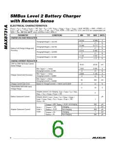
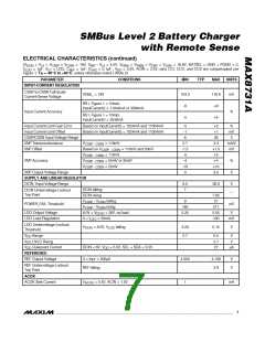
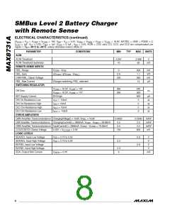
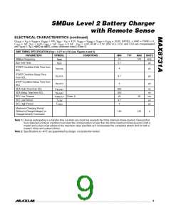
ELECTRICAL CHARACTERISTICS (continued)
(V
= V = V
= V
= 19V, V
- V = 4.5V, V
= V
= V
= V
= 16.8V, BATSEL = GND = PGND = 0,
CSIN
DCIN
LDO
LX
CSSP
CC
CSSN
BST
DAC
LX
FBSA
DD
FBSB
CSIP
C
= 1µF, V
= LDO, C
= 1µF, C
= 0.1µF , V
= 3.3V, ACIN = 2.5V; pins CCI, CCV, and CCS are compensated
REF
per Figure 1; T = -40°C to +85°C, unless otherwise noted.) (Note 2)
A
SMB TIMING SPECIFICATION (V
PARAMETERS
= 2.7V to 5.5V) (see Figures 4 and 5)
DD
SYMBOL
CONDITIONS
MIN
10
TYP
MAX
UNITS
kHz
SMBus Frequency
f
100
SMB
Bus Free Time
t
4.7
µs
BUF
START Condition Hold Time from
SCL
t
4
4.7
4
µs
µs
µs
HD:STA
START Condition Setup Time
from SCL
t
SU:STA
STOP Condition Setup Time from
SCL
t
SU:STO
SDA Hold Time from SCL
SDA Setup Time from SCL
SCL Low Timeout
t
300
250
25
ns
ns
ms
µs
µs
HD:DAT
t
SU:DAT
t
(Note 1)
35
TIMEOUT
SCL Low Period
T
LOW
4.7
4
SCL High Period
T
HIGH
Maximum Charging Period
Without a ChargeVoltage() or
ChargeCurrent() Command
140
210
s
Note 1: Devices participating in a transfer time out when any clock low exceeds the 25ms minimum timeout period. Devices that
have detected a timeout condition must reset the communication no later than the 35ms maximum timeout period. Both a
master and a slave must adhere to the maximum value specified as it incorporates the cumulative stretch limit for both a
master (10ms) and a slave (25ms).
Note 2: Specifications to -40°C are guaranteed by design, not production tested.
_______________________________________________________________________________________
9

 MAXIM [ MAXIM INTEGRATED PRODUCTS ]