MAX31865
RTD-to-Digital Converter
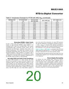
ADC. A delay time of at least five time constants plus an
additional 1ms (for the protection devices to stabilize) is
recommended to achieve specified accuracy.
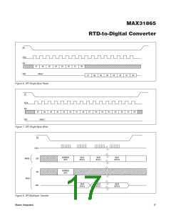
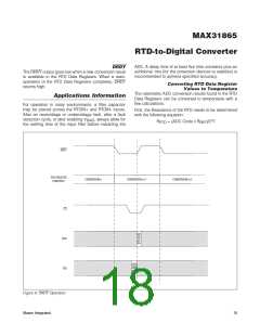
DRDY
The DRDY output goes low when a new conversion result
is available in the RTD Data Registers. When a read-
operation of the RTD Data Registers completes, DRDY
returns high.
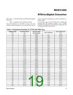
Converting RTD Data Register
Values to Temperature
The ratiometric ADC conversion results found in the RTD
Data Registers can be converted to temperature with a
few calculations.
Applications Information
For operation in noisy environments, a filter capacitor
may be placed across the RTDIN+ and RTDIN- inputs.
After an overvoltage or undervoltage fault, after a fault
First, the Resistance of the RTD needs to be determined
with the following equation:
detection cycle, or after enabling V
the settling time of the input filter before restarting the
, always allow for
BIAS
15
)/2
R
RTD
= (ADC Code x R
REF
DRDY
RTD REGISTER
CONVERSION n
CONTENTS
CONVERSION n+1
CONVERSION n+2
CS
SDO
SDI
Figure 9. DRDY Operation
Maxim Integrated
18

 MAXIM [ MAXIM INTEGRATED PRODUCTS ]