MAX17047/MAX17050
ModelGauge m3 Fuel Gauge
monitoring the acknowledge bit for presence of the
to the last byte it requires with a No Acknowledge. This
signals the device that control of SDA is to remain with
the master following the Acknowledge clock.
device. More complex formats such as the write Data,
read Data, and Function command protocols write data,
read data, and execute device-specific operations,
respectively. All bytes in each command format require
the slave or the host system to return an Acknowledge bit
before continuing with the next byte. Each function com-
mand definition outlines the required transaction format.
Table 6 applies to the transaction formats.
Write Data Protocol
The write Data protocol is used to write to register and
shadow RAM data to the IC starting at memory address
MAddr. Data0 represents the data written to MAddr,
Data1 represents the data written to MAddr + 1, and
DataN represents the last data byte written to MAddr +
N. The master indicates the end of a write transaction by
sending a STOP or Repeated START after receiving the
last acknowledge bit:
Basic Transaction Formats
Write: S SAddr W A MAddr A DataL A DataH A P
A write transaction transfers 1 or more data bytes to the
device. The data transfer begins at the memory address
supplied in the MAddr byte. Control of the SDA signal is
retained by the master throughout the transaction, except
for the Acknowledge cycles.
S SAddr W A MAddr A DataL0 A DataH0 A DataL1
A DataH1 A … DataLN A DataHN A P
The MSb of the data to be stored at address MAddr
can be written immediately after the MAddr byte is
acknowledged. Because the address is automatically
incremented after the least significant bit (LSb) of each
byte is received by the device, the MSb of the data at
address MAddr + 1 can be written immediately after the
acknowledgment of the data at address MAddr. If the
bus master continues an autoincremented write transac-
tion beyond address FFh, the device ignores the data.
Data is also ignored on writes to read-only addresses
but not reserved addresses. Do not write to reserved
address locations.
Read: S SAddr W A MAddr A Sr SAddr R A DataL A DataH N P
write Portion
read Portion
A read transaction transfers one or more words from the
IC. Read transactions are composed of two parts, a write
portion followed by a read portion, and are therefore
inherently longer than a write transaction. The write por-
tion communicates the starting point for the read opera-
tion. The read portion follows immediately, beginning with
a Repeated START, Slave Address with R/W set to a 1.
Control of SDA is assumed by the IC beginning with the
Slave Address Acknowledge cycle. Control of the SDA
signal is retained by the device throughout the transac-
tion, except for the Acknowledge cycles. The master
indicates the end of a read transaction by responding
Read Data Protocol
The read data protocol is used to read register and
shadow RAM data from the device starting at memory
address specified by MAddr. Data0 represents the data
byte in memory location MAddr, Data1 represents the
data from MAddr + 1, and DataN represents the last byte
read by the master:
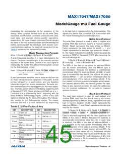
Table 6. 2-Wire Protocol Key
KEY
DESCRIPTION
START bit
KEY
DESCRIPTION
S SAddr W A MAddr A Sr SAddr R A DataL0 A
DataH0 A DataL1 A DataH1 A …DataLN N DataHN N P
S
Sr
Repeated START
Slave Address
(7 bit)
Data is returned beginning with the most significant bit
(MSb) of the data in MAddr. Because the address is
automatically incremented after the LSb of each byte
is returned, the MSb of the data at address MAddr +
1 is available to the host system immediately after the
acknowledgment of the data at address MAddr. If the
bus master continues to read beyond address FFh, the
device outputs data values of FFh. Addresses labeled
Reserved in the memory map return undefined data. The
bus master terminates the read transaction at any byte
boundary by issuing a No Acknowledge followed by a
STOP or Repeated START.
SAddr
FCmd
MAddr
Data
A
W
R
R/W bit = 0
R/W bit = 1
STOP bit
Function Command
byte
Memory Address
byte
P
Data byte written by
Master
Data byte returned
by Slave
Data
A
Acknowledge bit—
Master
Acknowledge bit—
Slave
No Acknowledge—
Master
No Acknowledge—
Slave
N
N
���������������������������������������������������������������� Maxim Integrated Products 45

 MAXIM [ MAXIM INTEGRATED PRODUCTS ]