Notebook CPU Step-Down Controller for Intel
-
Mobile Voltage Positioning (IMVP II)
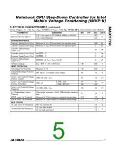
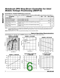
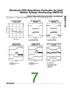
Typical Operating Characteristics (continued)
(Circuit of Figure 1, V+ = 12V, V = V = SKP/SDN = 5V, V
= 1.25V, T = +25°C, unless otherwise noted.)
DD
CC
OUT
A
OUTPUT VOLTAGE DISTRIBUTION
REFERENCE VOLTAGE DISTRIBUTION
25
20
15
10
5
25
V
= 1.25V
OUT
20
15
10
5
0
0
-0.48
-0.24
0.00
0.24
0.48
1.995
1.998
2.000
2.002
2.005
OUTPUT VOLTAGE ERROR (%)
REFERENCE VOLTAGE (V)
Pin Description
PIN
NAME
FUNCTION
Battery Voltage Sense Connection. Connect V+ to input power source. V+ is used only for PWM one-shot
timing. DH on-time is inversely proportional to input voltage over a range of 2V to 28V.
1
V+
Combined Shutdown and Skip-Mode Control. Drive SKP/SDN to GND for shutdown. Leave SKP/SDN open for
low-noise forced-PWM mode, or drive to V for pulse-skipping operation. Low-noise forced-PWM mode caus-
CC
2
SKP/SDN es inductor current recirculation at light loads and suppresses pulse-skipping operation. Forcing SKP/SDN to
12V to 15V disables both the overvoltage protection and undervoltage protection circuits and clears the fault
latch, with otherwise normal pulse-skipping operation. Do not connect SKP/SDN to > 15V.
Slew-Rate Adjustment Pin. Connect a resistor from TIME to GND to set the internal slew-rate clock. A 470kΩ
3
4
TIME
✕
to 47kΩ resistor sets the clock from 38kHz to 380kHz, f
= 150kHz 120kΩ / R
.
TIME
SLEW
FB
Feedback Input. Connect FB to the junction of the external inductor and the positioning resistor (Figure 1).
Feedback Offset Adjust Negative Input. The output shifts by an amount equal to the difference between POS
and NEG multiplied by a scale factor that depends on the DAC codes (see the Integrator Amplifiers/Output
Voltage Offsets section). Connect both POS and NEG to REF if the offset function is not used.
5
6
NEG
Integrator Capacitor Connection. Connect a 47pF to 1000pF (47pF typ) capacitor from CC to GND to set the
integration time constant (see the Integrator Amplifiers/Output Voltage Offsets section).
CC
Suspend-Mode Voltage Select Input. S0 and S1 are four-level digital inputs that select the suspend-mode
VID code for the suspend-mode multiplexer inputs. If SUS is high, the suspend-mode VID code is delivered
to the DAC (see the Internal Multiplexers (ZMODE/SUS) section).
7, 8
9
S0, S1
Analog Supply Voltage Input for PWM Core. Connect V
to the system supply voltage (4.5V to 5.5V) with a
CC
V
CC
series 20Ω resistor. Bypass to GND with a 0.22µF (min) capacitor.
_______________________________________________________________________________________
9

 MAXIM [ MAXIM INTEGRATED PRODUCTS ]