MAX14586/MAX14590
High-Current Overvoltage Protectors
with Adjustable OVLO
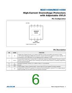
Pin Configuration
TOP VIEW
OUT
8
OUT
7
GND
6
I.C.
5
MAX14586
MAX14590
*EP
+
1
2
3
4
IN
IN
OVLO
I.C.
TDFN
(2mm x 2mm)
*CONNECT EXPOSED PAD TO GND.
Pin Description
PIN
NAME
FUNCTION
Voltage Input. Bypass IN with a 1FF ceramic capacitor as close as possible to the device to obtain
Q15kV Human Body Model (HBM) ESD protection. Connect both IN pins together for proper operation. IN
is protected to Q2kV HBM when IN is not bypassed with a capacitor to GND.
1, 2
IN
External OVLO Adjustment. Connect OVLO to GND when using the internal threshold. Connect a resistor-
divider to OVLO to set a different OVLO threshold; this external resistor-divider is completely independent
from the internal threshold.
3
OVLO
4, 5
6
I.C.
GND
OUT
Internally Connected. Connect I.C. to GND or leave I.C. unconnected.
Ground
7, 8
Output Voltage. Output of internal switch. Connect both OUT pins together for proper operation.
Exposed Pad. Connect EP to ground. For enhanced thermal dissipation, connect EP to a copper area as
large as possible. Do not use EP as the only ground connection.
—
EP
����������������������������������������������������������������� Maxim Integrated Products
6

 MAXIM [ MAXIM INTEGRATED PRODUCTS ]