Half-Duplex RS-485-/RS-422-Compatible
Transceiver with AutoDirection Control
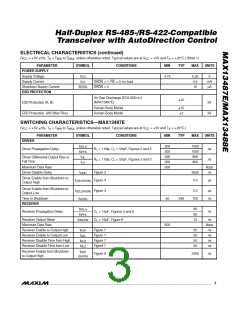
SWITCHING CHARACTERISTICS—MAX13488E (continued)
(V
= +5V 5ꢃ, T = T
to T
, unless otherwise noted. Typical values are at V
= +5V and T = +25°C.)
CC A
CC
A
MIN
MAX
PARAMETER
SYMꢁOL
CONDITIONS
MIN
TYP
MAX
UNITS
Receiver Enable from Shutdown
to Output Low
t
RZL
(SꢁDN)
Figure 8
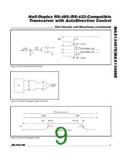
Figure 3
2200
ns
Receiver Enable Delay
Time to Shutdown
t
70
ns
ns
RED
t
50
340
700
SꢁDN
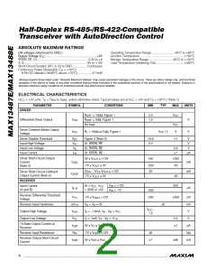
Note 1: All currents into the device are positive. All currents out of the device are negative. All voltages referred to device ground,
unless otherwise noted.
Note 2: This is a differential voltage from A to ꢂ that the driving device must see on the bus to disable its driver.
Note 3: The short-circuit output current applied to peaꢀ current just prior to foldbacꢀ current limiting. The short-circuit foldbacꢀ out-
put current applies during current limiting to allow a recovery from bus contention.
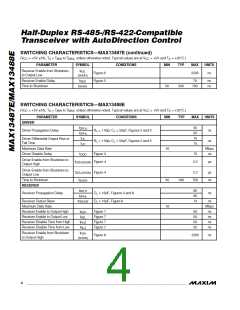
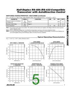
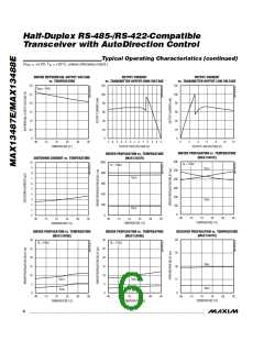
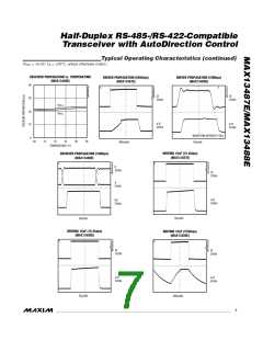
Typical Operating Characteristics
(V
= +5.0V, T = +25°C, unless otherwise noted.)
A
CC
OUTPUT CURRENT
vs. RECEIVER OUTPUT-HIGH VOLTAGE
OUTPUT CURRENT
vs. RECEIVER OUTPUT-LOW VOLTAGE
SUPPLY CURRENT vs. TEMPERATURE
4.0
35
28
21
14
7
60
50
40
30
20
10
0
NO LOAD
3.8
3.6
3.4
3.2
3.0
0
-40
-15
10
35
60
85
0
1
2
3
4
5
0
1
2
3
4
5
TEMPERATURE (°C)
OUTPUT-HIGH VOLTAGE (V)
OUTPUT-LOW VOLTAGE (V)
RECEIVER OUTPUT-LOW
VOLTAGE vs. TEMPERATURE
RECEIVER OUTPUT-HIGH VOLTAGE
vs. TEMPERATURE
DIFFERENTIAL OUTPUT CURRENT
vs. DIFFERENTIAL OUTPUT VOLTAGE
0.5
0.4
0.3
0.2
0.1
0
5.4
5.2
5.0
4.8
4.6
4.4
4.2
4.0
80
60
40
20
0
I = 1mA
O
I
= 1mA
O
-40
-15
10
35
60
85
-40
-15
10
35
60
85
0
1
2
3
4
5
TEMPERATURE (°C)
TEMPERATURE (°C)
OUTPUT VOLTAGE (V)
_______________________________________________________________________________________
5

 MAXIM [ MAXIM INTEGRATED PRODUCTS ]