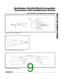
Half-Duplex RS-485-/RS-422-Compatible
Transceiver with AutoDirection Control
SWITCHING CHARACTERISTICS—MAX13487E (continued)
(V
= +5V 5ꢃ, T = T
to T
, unless otherwise noted. Typical values are at V
= +5V and T = +25°C.)
CC A
CC
A
MIN
MAX
PARAMETER
SYMꢁOL
CONDITIONS
MIN
TYP
MAX
UNITS
Receiver Enable from Shutdown
to Output Low
t
RZL
(SꢁDN)
Figure 8
Figure 3
2200
ns
Receiver Enable Delay
Time to Shutdown
t
70
ns
ns
RED
t
50
340
700
SꢁDN
SWITCHING CHARACTERISTICS—MAX13488E
(V
= +5V 5ꢃ, T = T
to T
, unless otherwise noted. Typical values are at V
= +5V and T = +25°C.)
CC A
CC
A
MIN
MAX
PARAMETER
SYMꢁOL
CONDITIONS
MIN
TYP
MAX
UNITS
DRIVER
t
t
50
50
15
15
DPLꢁ
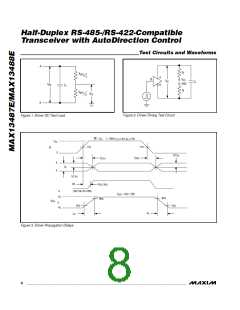
Driver Propagation Delay
R = 110Ω, C = 50pF, Figures 2 and 3
ns
ns
L
L
DPꢁL
t
t
ꢁL
Driver Differential Output Rise or
Fall Time
R = 110Ω, C = 50pF, Figures 2 and 3
L
L
Lꢁ
Maximum Data Rate
Driver Disable Delay
16
Mbps
ns
t
Figure 3
Figure 4
70
DDD
Driver Enable from Shutdown to
Output ꢁigh
t
2.2
µs
DZꢁ(SꢁDN)
Driver Enable from Shutdown to
Output Low
t
Figure 4
2.2
µs
ns
DZL(SꢁDN)
Time to Shutdown
t
50
16
340
700
SꢁDN
RECEIVER
t
80
80
13
RPLꢁ
Receiver Propagation Delay
C = 15pF, Figures 5 and 6
L
ns
t
RPꢁL
Receiver Output Sꢀew
t
C = 15pF, Figure 6
L
ns
Mbps
ns
RSKEW
Maximum Data Rate
Receiver Enable to Output ꢁigh
Receiver Enable to Output Low
Receiver Disable Time from ꢁigh
Receiver Disable Time from Low
t
t
Figure 7
Figure 7
Figure 7
Figure 7
50
50
50
50
RZꢁ
t
ns
RZL
ns
RꢁZ
t
ns
RLZ
Receiver Enable from Shutdown
to Output ꢁigh
t
RZꢁ
Figure 8
2200
ns
(SꢁDN)
4
_______________________________________________________________________________________

 MAXIM [ MAXIM INTEGRATED PRODUCTS ]