Half-Duplex RS-485-/RS-422-Compatible
Transceiver with AutoDirection Control
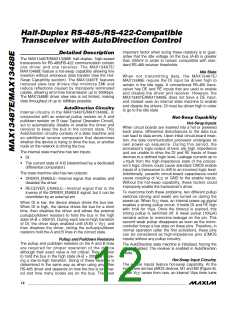
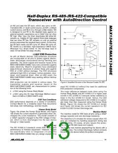
on M2 and sets the SR latch, which also turns on M1.
Transistors M2, a 1.5mA current source, and M1, a 500µA
current source, pull RE to V through a 5ꢀΩ resistor. M2
CC
is designed to pull RE to the disabled state against an
external parasitic capacitance up to 100pF that can drive
RE high. After 15µs, the timer deactivates M2 while M1
remains on, holding DI high against three-state leaꢀages
that can drive RE low. M1 remains on until an external
source overcomes the required input current. At this time,
the SR latch resets and M1 turns off. When M1 turns off,
RE reverts to a standard, high-impedance CMOS input.
V
CC
15µs
TIMER
TIMER
SR LATCH
Whenever V
drops below 1V, the hot-swap input is
CC
reset. DI has similar hot-swap circuitry.
15ꢀk ESD Protection
As with all Maxim devices, ESD-protection structures
are incorporated on all pins to protect against electro-
static discharges encountered during handling and
assembly. The driver outputs and receiver inputs of the
MAX13487E/MAX13488E have extra protection against
static electricity. Maxim’s engineers have developed
state-of-the-art structures to protect these pins against
ESD of 15ꢀV without damage. The ESD structures
withstand high ESD in all states: normal operation, shut-
down, and powered down. After an ESD event, the
MAX13487E/MAX13488E ꢀeep worꢀing without latchup
or damage.
5kΩ
RE
RE
(HOT SWAP)
100µA
500µA
M1
M2
V
CC
ESD protection can be tested in various ways. The
transmitter outputs and receiver inputs of the
MAX13487E/MAX13488E are characterized for protec-
tion to the following limits:
Figure 9. Simplified Structure of the Receiver Enable Pin (RE)
meet IEC 61000-4-2 without the need for additional
ESD-protection components.
•
•
15ꢀV using the ꢁuman ꢂody Model
The major difference between tests done using the
ꢁuman ꢂody Model and IEC 61000-4-2 is higher peaꢀ
current in IEC 61000-4-2 because series resistance is
lower in the IEC 61000-4-2 model. ꢁence, the ESD
withstand voltage measured to IEC 61000-4-2 is gener-
ally lower than that measured using the ꢁuman ꢂody
Model. Figure 10c shows the IEC 61000-4-2 model,
and Figure 10d shows the current waveform for IEC
61000-4-2 ESD Contact Discharge test.
15ꢀV using the Air Gap Discharge Method speci-
fied in 61000-4-2 (MAX13487E only)
ESD Test Conditions
ESD performance depends on a variety of conditions.
Contact Maxim for a reliability report that documents
test setup, test methodology, and test results.
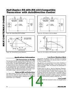
Human Body Model
Figure 10a shows the ꢁuman ꢂody Model, and Figure
10b shows the current waveform it generates when dis-
charged into a low impedance. This model consists of
a 100pF capacitor charged to the ESD voltage of inter-
est, which is then discharged into the test device
through a 1.5ꢀΩ resistor.
Machine Model
The machine model for ESD tests all pins using a 200pF
storage capacitor and zero discharge resistance.
The objective is to emulate the stress caused when I/O
pins are contacted by handling equipment during test
and assembly. Of course, all pins require this protec-
tion, not just RS-485 inputs and outputs.
IEC 61000-4-2
The IEC 61000-4-2 standard covers ESD testing and
performance of finished equipment. ꢁowever, it does
not specifically refer to integrated circuits. The
MAX13487E/MAX13488E help you design equipment to
The Air-Gap test involves approaching the device with a
charged probe. The Contact-Discharge method connects
the probe to the device before the probe is energized.
______________________________________________________________________________________ 13

 MAXIM [ MAXIM INTEGRATED PRODUCTS ]