Half-Duplex RS-485-/RS-422-Compatible
Transceiver with AutoDirection Control
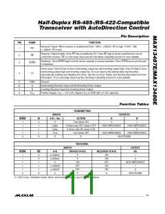
Pin Description
PIN
NAME
FUNCTION
Receiver Output. When receiver is enabled and V(A) - V(ꢂ) > +200mV, RO is high. If V(A) - V(ꢂ)
< -200mV, RO is low.
1
RO
Receiver Output Enable. Drive RE low to enable the RO. Drive RE high to let the AutoDirection circuit
control the receiver. RE is a hot-swap input (see the Hot-Swap Capability section for more details).
2
3
RE
Shutdown. Drive SHDN high to let the device operate in normal operation. Drive SHDN low to put the part
in shutdown.
SHDN
Driver Input. Drive DI low to force noninverting output low and inverting output high. Drive DI high to force
noninverting output high and inverting output low. DI is an input to the internal state machine that
automatically enables and disables the driver. See the Function Tables and General Description for more
information. DI is a hot-swap input (see the Hot-Swap Capability section for more details).
4
DI
5
6
7
8
GND
A
Ground
Noninverting Receiver Input and Noninverting Driver Output
Inverting Receiver Input and Inverting Driver Output
ꢂ
V
Positive Supply, V
= +5V 5ꢃ. ꢂypass V
to GND with a 0.1µF capacitor.
CC
CC
CC
Function Tables
TRANSMITTING
INPUTS
A-ꢁ > V
OUTPUTS
SHDN
DI
0
ACTION
Turn driver ON
A
ꢁ
DT
1
1
1
1
0
X
0
1
1
False
False
True
X
If driver was OFF, ꢀeep it OFF
If driver was ON, ꢀeep it ON
Turn driver OFF
ꢁIGꢁ IMPEDANCE
1
ꢁIGꢁ IMPEDANCE
0
1
1
ꢁIGꢁ IMPEDANCE
ꢁIGꢁ IMPEDANCE
X
X
SꢁUTDOWN
RECEIVING
INPUTS
OUTPUT
SHDN
RE
0
A-ꢁ
DRIVER STATE
RECEIVER STATE
RO
1
1
1
1
1
0
≥+200mV
≤-200mV
X
X
X
ON
ON
OFF
ON
ON
X
1
0
0
1
ON
OFF
OFF
X
ꢁIGꢁ IMPEDANCE
1
>+200mV
≤-200mV
X
1
1
0
X
SꢁUTDOWN
X = Don’t care, shutdown mode, driver, and receiver outputs are in high impedance.
______________________________________________________________________________________ 11

 MAXIM [ MAXIM INTEGRATED PRODUCTS ]